EMI Filter Design Fundamentals – Calculations, Impedance, and Multi-Stage Solutions
Having selected screw-type EMI filters for your application, the next challenge is verifying that the chosen design will actually deliver the required attenuation in your specific system. The technical parameters, calculation methods, and design trade-offs that electrical engineers and advanced procurement professionals must understand to validate filter performance and justify design decisions.
Understanding Attenuation and Frequency Response
Attenuation Definition and Decibel Basics
Attenuation quantifies how much a filter reduces signal amplitude at a given frequency, expressed in decibels (dB).
Formula: Attenuation (dB) = 20 × log₁₀(Vin / Vout)
Where:
- Vin = Input signal amplitude
- Vout = Output signal amplitude
Reading Frequency Response Curves
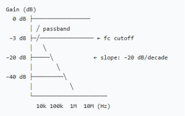
A filter’s frequency response plots gain or attenuation across the frequency spectrum. Understanding the curve is essential for verifying that a filter addresses your actual noise frequencies, not just theoretical worst cases.
Typical single-stage LC filter response:
Critical Calculations and Derivations
Corner Frequency (Cutoff Frequency) Calculation
For a simple LC network, the –3 dB cutoff frequency is:
fc = 1 / (2π√LC)
Where:
- fc = Cutoff frequency in Hz
- L = Inductance in Henries
- C = Capacitance in Farads
- π ≈ 3.14159
Attenuation Slope and Multi-Decade Performance
A first-order filter’s attenuation increases by 20 dB for every 10× increase in frequency:
If attenuation @ 100 kHz = 20 dB
Then attenuation @ 1 MHz (10× higher) = 20 + 20 = 40 dB
For second-order filters, the slope is steeper:
If attenuation @ 100 kHz = 40 dB
Then attenuation @ 1 MHz = 40 + 40 = 80 dB
Implication: If your EMC standard limits conducted emissions at 1 MHz but your single-stage filter attenuation is marginal at that frequency, cascading a second filter stage or selecting a two-stage integrated design becomes necessary.
Leakage Current Calculation
Leakage current arises from Y-capacitors and is determined by:
I\_leak = V × 2πfC
Where:
- I_leak = Leakage current in Amperes
- V = Applied voltage (RMS) in Volts
- f = Frequency in Hz
- C = Total Y-capacitance in Farads
Impedance Matching and Real-World Performance
Why Source Impedance Matters
Insertion loss values in datasheets typically assume a specific source impedance—commonly 50 Ω, which matches radio-frequency test fixtures but may not match your actual system.
In practical power-entry circuits:
- Low-impedance sources(e.g., large input filter capacitors): 5–50 Ω
- Moderate-impedance sources(e.g., medium inductance, limited filtering): 50–200 Ω
- High-impedance sources(e.g., series line reactors, low-current supplies): 200 Ω and above
Mitigating Impedance Mismatch
If source impedance is excessively low:
Add a series impedance element (common-mode reactor or line inductor) upstream of the filter to raise the source impedance and restore coupling efficiency.
If source impedance is excessively high:
Fit damping resistance at filter output to eliminate resonant peaks and smooth frequency response.
Thermal Design and Derating
Power Dissipation and Temperature Rise
EMI filters dissipate power primarily through inductor DCR (DC resistance) and core losses. Resistive losses are temperature-dependent and worsen as the filter ages.
Primary loss mechanism: P\_loss = I² × R\_ESR
Where R\_ESR is the equivalent series resistance of the inductor.
Derating and Thermal Margin
The filter’s rated current drops with rising operating temperature. Standard practice derates current by 1% to 2% per °C above the rated ambient temperature. To reserve thermal safety margin over full working temperature range, specify a filter with nominal current at least 1.5 times the equipment’s peak operating current.
Conclusion – From Theory to Practice
Successful EMI filter selection requires more than reading attenuation curves from datasheets. You must:
1.Calculate your required attenuation based on your measured or estimated noise and your EMC standard limits.
2.Understand frequency response trade-offs and decide whether single or multi-stage filtering fits your cost and performance envelope.
3.Account for source and load impedance and verify that the vendor’s attenuation estimate is realistic for your circuit.
4.Plan for thermal performance and ensure that derating curves support your operating environment.
5.Validate with samples if the application is critical; field performance often differs from laboratory conditions.
By anchoring your decision in these technical fundamentals, you reduce the risk of post-design surprises and improve the likelihood that your EMI filtering solution will meet compliance goals on the first attempt.
Need Help Selecting LCA Screw-Type EMI Filters?
Every equipment design is unique, and so are on-site EMC challenges. LCA’s engineering team helps you calculate required attenuation, analyze system impedance, assess thermal derating demands and match single/multi-stage topologies against your EMC standards and operating conditions. Reach out to LCA for personalized technical consultation and targeted filter recommendations to pass EMC compliance smoothly on the first try.