PLC control cabinets are among the more demanding EMC environments in industrial electronics. Switching power supplies, relay outputs, variable frequency drives, and digital I/O interfaces often share the same enclosure or the same power distribution network. Each generates conducted noise; together, they create an aggregate noise environment at every cable entry point that is more complex than any single source.
Feedthrough capacitors — mounted at the panel wall where conductors enter and exit the enclosure — are one of the most effective tools for managing conducted noise at these boundary points. This article explains where and why they are used in PLC systems, how to select them, what purchasing engineers need to verify, and where they are not the right solution.
Why PLC Cabinets Are Difficult EMC Environments
Multiple Noise Sources Operating Simultaneously
A PLC cabinet typically contains several independent noise sources: switching mode power supplies on the 24V DC control rail, relay coils switching inductive loads, VFDs or servo drives on motor control lines, and high-speed digital I/O cycling at the processor clock rate. These sources do not operate in isolation — their conducted noise appears on shared power rails, couples onto adjacent signal cables, and propagates along field wiring that runs from the cabinet to sensors and actuators.
The result is that any single cable entry point is exposed to the combined noise from all active sources, not just the one closest to it. Filter design that addresses each entry point based on a single assumed source may underperform when multiple sources contribute simultaneously.
How Conducted Noise Affects PLC Reliability
Common-mode noise on I/O cables — appearing on both conductors simultaneously relative to chassis ground — is the dominant interference mechanism at most PLC cabinet entry points. If this noise reaches digital I/O modules, it can cause false input states or missed output transitions. On analog sensor lines, it appears as measurement offset or noise floor elevation. On fieldbus communication lines, it can cause parity errors, frame drops, or complete communication failure.
These effects are often intermittent and difficult to reproduce, which makes them particularly expensive to diagnose in installed systems. Prevention at the design stage is substantially less costly than field troubleshooting.
The Case for Boundary Filtering
Why Placement at the Panel Wall Matters
A filter component is most effective when placed at the point where the conductor it protects crosses the enclosure boundary — the panel wall. A feedthrough capacitor installed at the panel wall shunts common-mode noise to chassis ground before the noise enters the shielded volume of the cabinet. There is no length of unfiltered cable inside the enclosure that can radiate or couple noise onto adjacent circuits.
A PCB-mount capacitor placed inside the cabinet, some distance from the panel entry, allows an unfiltered segment of cable to run through the interior. That segment is exposed to noise from other sources inside the cabinet and can re-radiate before the filter is reached. Boundary placement eliminates this exposure.
How Feedthrough Geometry Provides an Advantage at High Frequencies
In a standard two-terminal shunt capacitor, noise current must travel into one lead, through the capacitor body, and out the other lead to reach ground. This path introduces parasitic inductance (ESL). Above the component’s self-resonant frequency (SRF), the inductive reactance dominates and the capacitor stops attenuating.
In a feedthrough capacitor, the conductor passes through the component body. Noise is coupled capacitively from the through-conductor to the outer electrode — which bonds directly to the chassis — without requiring the current to reverse direction. This geometry reduces the parasitic inductance in the shunt path and extends the frequency range over which the component remains capacitive and attenuates. For PLC systems where conducted noise from drives and SMPS extends into the MHz range, this high-frequency advantage is often the determining factor in choosing feedthrough types over PCB-mount alternatives.
Where to Use Feedthrough Capacitors in a PLC System
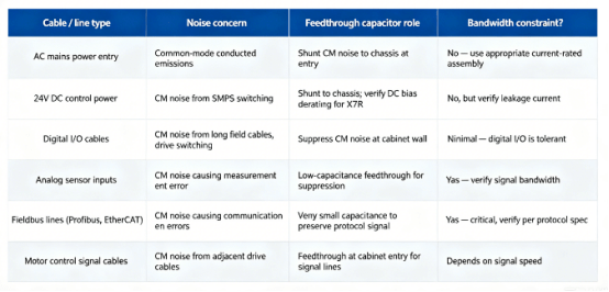
Not every conductor in a PLC cabinet requires a feedthrough capacitor. The primary candidates are conductors that cross the enclosure boundary and carry high-frequency noise or connect to noise-sensitive circuits.
| Cable / line type | Noise concern | Feedthrough capacitor role | Bandwidth constraint? |
| AC mains power entry | Common-mode conducted emissions | Shunt CM noise to chassis at entry | No — use appropriate current-rated assembly |
| 24V DC control power | CM noise from SMPS switching | Shunt to chassis; verify DC bias derating for X7R | No, but verify leakage current |
| Digital I/O cables | CM noise from long field cables, drive switching | Suppress CM noise at cabinet wall | Minimal — digital I/O is tolerant |
| Analog sensor inputs | CM noise causing measurement error | Low-capacitance feedthrough for CM suppression | Yes — verify signal bandwidth |
| Fieldbus lines (Profibus, EtherCAT) | CM noise causing communication errors | Very small capacitance to preserve protocol signal | Yes — critical, verify per protocol spec |
| Motor control signal cables | CM noise from adjacent drive cables | Feedthrough at cabinet entry for signal lines | Depends on signal speed |
For high-current three-phase power entries (VFD supply lines), single-conductor feedthrough capacitors are not appropriate without verifying that the specific component’s current rating and leakage current specification match the application. Dedicated three-phase EMI filter assemblies are typically required for these entries.
Technical Selection Criteria
Identify the Noise Mode First
Feedthrough capacitors provide a low-impedance shunt path from the line conductor to chassis ground — which directly addresses common-mode noise. Differential-mode noise, appearing between the active conductors, requires series inductance in the signal path, which the capacitor alone does not provide. If differential-mode noise is dominant, a capacitor-only solution will be inadequate. Confirming the noise mode through measurement before specifying a component avoids the most common filter misapplication in PLC system design.
Capacitance Value and SRF
Select capacitance based on the target noise frequency — not the maximum available value. Increasing capacitance lowers the SRF. If the SRF of the larger capacitor falls below the noise frequency of concern, the component is operating in its inductive region and provides less attenuation than a smaller capacitor with a higher SRF. Verify the SRF from the specific component’s datasheet against the highest noise frequency in the system.
Dielectric Selection for DC Control Lines
On 24V DC control power lines, X7R dielectric capacitors lose a significant fraction of their nominal capacitance under applied DC bias. The magnitude of this derating is product- specific and must be confirmed from the manufacturer’s DC bias derating curve for the exact part number at the actual operating voltage. C0G (NP0) dielectric is stable under DC bias and is the more reliable choice for DC power line applications where consistent filter performance across the operating voltage range is required.
Leakage Current and RCD Compatibility
Each feedthrough capacitor connected to earth contributes a leakage current under operating conditions. In a PLC cabinet with multiple filtered cable entries, the aggregate leakage current from all filter capacitors must remain below the trip threshold of the RCD protecting the circuit, with appropriate margin. This calculation requires the leakage current specification from each component’s datasheet — not a single assumed value. Perform the aggregate sum before finalizing capacitance values, particularly for mains-connected entries.
Signal Bandwidth Constraints for Fieldbus and Analog Lines
On fieldbus lines (Profibus, EtherCAT, CANopen) and analog sensor inputs, filter capacitance adds load to the signal path. Excessive capacitance degrades signal rise times and can cause communication errors on protocols with defined bandwidth requirements. The acceptable capacitance limit is protocol- and implementation-specific; no single universal value applies across all configurations. For these lines, use the minimum capacitance that provides adequate noise attenuation at the interference frequency while keeping the filter’s effect on the signal passband within the limits specified by the protocol standard and the transceiver manufacturer’s application guidance. Verify by testing in the actual circuit.
Conclusion
Feedthrough capacitors solve a core PLC problem: multiple noise sources create complex EMI at every cable entry. Mounted at the panel wall, they shunt noise to ground at the boundary—no unfiltered cable inside. Their low-ESL geometry extends filtering into the MHz range. Success requires identifying noise mode , selecting capacitance by noise frequency , and checking SRF, DC bias, leakage, and signal bandwidth.
Based on LCA’s experience, proper selection and boundary placement improve PLC reliability and simplify compliance testing.
Frequently Asked Questions
Q: Where exactly in a PLC cabinet should feedthrough capacitors be installed? At the panel wall — the point where each cable crosses the enclosure boundary. This places the noise shunt at the shield entry point and eliminates any unfiltered cable length inside the cabinet. Filters placed inside the cabinet, away from the panel wall, allow unfiltered cable to run through the interior and can re-couple noise from other sources before the filter is reached.
Q: How does leakage current from feedthrough capacitors affect RCD protection? Each feedthrough capacitor connected to earth contributes to the total earth leakage current of the circuit. In a cabinet with multiple filtered entries, the aggregate leakage may be significant. Sum the leakage current specifications for all filter components from their individual datasheets and compare against the RCD trip threshold, applying appropriate margin. This is a required design calculation for mains-connected PLC systems, not an optional check.
Q: Why does the dielectric type matter on a 24V DC control line? X7R dielectric capacitors experience significant capacitance reduction under applied DC bias. On a 24V DC line, the effective capacitance may be substantially lower than the nominal value, which shifts the filter’s cutoff frequency and reduces attenuation at the target frequency. C0G dielectric is stable under DC bias and is more reliable for consistent filter performance on DC control lines. Always check the DC bias derating curve in the specific component’s datasheet.
Q: If the PLC cabinet passes EMC testing without feedthrough capacitors on signal lines, are they still needed? If the system demonstrates compliance without them, that reflects the test configuration. EMC test results are configuration-specific — they represent the cable lengths, routing, and load conditions of the test setup. Field installations with longer cable runs or different routing may perform differently. Feedthrough capacitors at signal entries reduce sensitivity to these installation variables and can improve margin against the limits. Whether they are required is a risk decision based on the test results and the expected variability of field installations.
Need Help Improving EMC Performance in Your PLC Cabinet?
Every control cabinet is different — and so is every EMI challenge.
LCA’s engineering team can help you understand common-mode noise suppression, selection criteria, installation practices, and leakage current considerations — and recommend the right feedthrough capacitor solution for your PLC system.
Contact LCA today for one-to-one technical support and customized EMI suppression recommendations.