The terms “EMI filter” and “RF filter” appear in datasheets, procurement catalogs, and standards documents with enough overlap to cause genuine confusion. Some EMI filters are technically low-pass RF filters. Some RF components are used for interference suppression.
This article draws a clear technical distinction between the two categories, explains where they overlap, and provides a practical framework for deciding which type is appropriate for a given OEM design.
Why Distinction Matters
Where Confusion Typically Arises
Both filter types suppress unwanted signals. Both can be described by insertion loss curves. Both may operate in overlapping frequency ranges — the upper boundary of the conducted emissions band (30 MHz under CISPR standards for many equipment categories) overlaps with the lower end of many RF filter applications. Suppliers sometimes use “EMI/RFI filter” as a combined label, which does not indicate that the component is optimized for both purposes.
The core difference is not frequency range — it is the impedance environment and the design objective. EMI filters are designed for uncontrolled, variable-impedance power and signal line environments. RF filters are designed for controlled, defined-impedance signal paths, typically 50 ohms. Applying either type outside its intended impedance environment produces results that may be substantially different from the datasheet specification.
Consequences of Specifying the Wrong Type
Installing EMI power-line filters onto RF signal paths causes:
- Excessive passband insertion loss
- Damaged RF impedance matching status
- Undesirable distortion of valid RF signals
Substituting narrow-band RF filters for EMI suppression leads to:
- Incomplete noise attenuation for out-of-stopband interference
- Uncontrolled residual conducted noise across wide frequency spectrum
Either misapplication results in:
- System performance deviating from design targets
- Failed EMC compliance or signal integrity testing
- Hard-to-locate troubleshooting due to improper filter classification
What Is an EMI Filter?
An EMI filter is a passive network designed to suppress conducted electromagnetic noise on power or signal lines. Its primary function is protection: preventing a device from radiating conducted interference onto shared lines (emissions) and preventing external conducted noise from reaching sensitive circuits inside the device (immunity).
Operating Frequency Range
Most EMI filters target the conducted emissions frequency range defined by applicable standards. Under CISPR 32 / EN 55032 and related standards, this range typically spans 150 kHz to 30 MHz for industrial and commercial equipment. Some filter designs extend below 150 kHz for power electronics applications; some feedthrough-type filters using low-inductance ceramic capacitors provide suppression above 30 MHz into the lower RF range.
Impedance Environment
EMI filters for power line applications are designed to operate in circuits where source and load impedance is not controlled and may vary significantly with frequency and operating conditions. The performance of an EMI filter in service depends on the actual system impedance, which often differs from the standardized test conditions used to generate datasheet insertion loss curves.
Common Topologies
EMI filters are typically built from capacitors, inductors, common-mode chokes, or feedthrough structures in C, L-C, Pi, or T configurations. The choice of topology determines whether the filter primarily suppresses common-mode noise, differential-mode noise, or both.
What Is an RF Filter?
An RF filter is a frequency-selective passive network designed to pass, reject, or shape signals within a defined frequency band in a controlled-impedance signal path. Unlike EMI filters, the design objective is not simply to suppress everything above a threshold — it is to provide a precise frequency response with defined passband behavior, rolloff characteristics, and out-of-band rejection.
Operating Frequency Range
RF filters span an extremely wide range, from a few MHz to GHz and beyond, depending on the application. A transmitter harmonic filter may operate at 400 MHz. A GPS front-end bandpass filter may operate at 1.575 GHz. A cellular diplexer may cover multiple bands simultaneously. The range is application-defined, not category-defined.
Impedance Environment
RF filters are designed for controlled transmission-line environments, most commonly 50 ohms. Return loss and impedance match are specified parameters for RF filters, not incidental characteristics. Inserting an RF filter into a circuit with impedance significantly different from its design environment shifts the frequency response, degrades return loss, and may substantially change the passband and stopband behavior.
Common Types
RF filters include low-pass, high-pass, bandpass, band-stop (notch), and diplexer configurations. Implementations range from lumped LC networks to distributed microstrip structures, surface acoustic wave (SAW) devices, ceramic resonator filters, and cavity filters, depending on frequency and selectivity requirements.
Key Differences: Side-by-Side Comparison
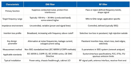
| Characteristic | EMI filter | RF filter |
| Primary function | Suppress conducted noise; protect from interference | Pass or reject defined frequency bands; shape signal |
| Target frequency range | Typically 150 kHz – 30 MHz (conducted band); some extend higher | MHz to GHz range; application-specific |
| Impedance environment | Uncontrolled, variable (power and signal lines) | Controlled, defined (typically 50Ω) |
| Insertion loss profile | Broadband, increasing with frequency above cutoff | Selective: low loss in passband, high rejection outside |
| Key design parameters | Attenuation at noise frequencies; leakage current; voltage/current rating | Passband insertion loss; return loss; band edges; selectivity |
| Measurement method | Non-50Ω standardized test (IEC 60939-3 / CISPR methods) | S-parameters in 50Ω system (network analyzer) |
| Applicable standards | IEC 60939-3, CISPR 32, IEC 61000 series, CE EMC Directive | System/interface specifications; FCC, ETSI, ITU spurious emission limits |
| Typical installation | Power entry, chassis feedthrough, cabinet I/O | RF signal path, antenna interface, receiver front end |
When to Use an EMI Filter
EMI filters are the appropriate choice when the problem is conducted electromagnetic interference on power or signal lines, and the objective is compliance with EMC standards or protection of sensitive electronics from supply line noise.
Typical use cases include:
Conducted emissions compliance: Equipment subject to CISPR 11, CISPR 32, EN 55011, or equivalent standards requires suppression of conducted noise injected onto the power supply network. EMI filters at the power entry address this requirement.
Industrial power electronics: VFDs, servo drives, switching power supplies, and motor controllers generate significant conducted noise at switching frequencies and their harmonics. EMI filters at panel entry points suppress this noise before it propagates into other parts of the system.
Cabinet and enclosure I/O: Signal lines entering shielded enclosures need filtering at the point of entry to maintain enclosure shielding effectiveness. Feedthrough-style EMI filters address this at the panel wall.
Conducted immunity: IEC 61000-4-6 tests the ability of equipment to withstand conducted RF disturbances on supply and signal lines. EMI filters improve immunity by reducing the level of injected interference that reaches sensitive circuits.
When to Use an RF Filter
RF filters are appropriate when the design requirement involves frequency-selective signal processing in a controlled impedance environment — passing or rejecting specific bands with precision.
Typical use cases include:
Transmitter spurious emission suppression: A low-pass filter at a transmitter output attenuates harmonics and spurious signals that would otherwise violate FCC, ETSI, or ITU spurious emission limits.
Receiver selectivity: Bandpass filters at receiver inputs reject out-of-band signals before the low-noise amplifier, reducing susceptibility to interference and preventing overload from adjacent channels.
Antenna interface filtering: Diplexers, duplexers, and bandpass filters at antenna ports separate transmit and receive signals or restrict the frequency range presented to the antenna.
Co-site interference management: When multiple transmitters and receivers operate in physical proximity, RF filtering prevents interference between systems sharing the same platform.
Selection Decision Framework
| Question | Answer indicates |
| Is the problem conducted noise on a power or signal line? | EMI filter |
| Is the frequency range primarily 150 kHz – 30 MHz? | EMI filter |
| Is the impedance environment variable and uncontrolled? | EMI filter |
| Is the objective broadband noise suppression? | EMI filter |
| Is the problem signal selectivity or band rejection in an RF path? | RF filter |
| Is the frequency range in the MHz–GHz range for a specific band? | RF filter |
| Is the impedance environment controlled (typically 50 ohms)? | RF filter |
| Does passband insertion loss and rolloff precision matter? | RF filter |
| Does the design include both a power entry and an RF signal path? | Both may be needed |
Conclusion
EMI filters and RF filters are not interchangeable. The core difference is impedance environment, not frequency range. EMI filters handle variable-impedance power lines (150 kHz–30 MHz). RF filters work in controlled 50-ohm signal paths (MHz–GHz).
Using the wrong type causes failures: signal distortion or unattenuated noise.
Based on LCA’s experience, match the filter to your problem—EMI for conducted noise on power lines, RF for signal selectivity.
Frequently Asked Questions
Q: Can an EMI filter and an RF filter be used interchangeably? Generally no. The two types are optimized for different impedance environments. An EMI filter designed for power line use does not provide the passband control or impedance matching required in a 50-ohm RF signal path. An RF filter placed on a power line will not perform as specified because the impedance conditions differ from its design environment.
Q: What frequency range does an EMI filter cover? Most EMI filters target the conducted emissions range, which for many equipment categories under CISPR standards spans 150 kHz to 30 MHz. Some designs extend below 150 kHz for power electronics applications; some feedthrough-style filters using low-inductance ceramics provide suppression above 30 MHz into the lower RF range. The exact range is product-specific and should be confirmed from the datasheet.
Q: What is the key difference between an EMI filter and a low-pass RF filter? Both attenuate signals above a cutoff frequency, but they serve different purposes. An EMI filter suppresses conducted noise in a variable-impedance environment without regard for passband signal integrity. A low-pass RF filter provides a defined passband with controlled rolloff and impedance match in a 50-ohm signal path. Design criteria, component selection, and characterization methods differ between the two.
Q: Why are insertion loss values from EMI and RF filter datasheets not comparable? EMI filter insertion loss is measured in a test environment that reflects variable or non-50-ohm source and load impedances. RF filter S-parameters are measured in a controlled 50-ohm system. Because the test conditions differ, numerical dB values from the two measurement methods are not directly comparable.
Q: Can a single component address both EMI suppression and RF signal filtering? Some broadband feedthrough or chip-type EMI filter components have effective suppression ranges extending into the lower RF spectrum, providing partial overlap. However, addressing both power-line conducted EMI suppression and precise RF signal selectivity with a single passive component is generally not achievable. Applications with both requirements typically need separate components optimized for each function.
References
1.IEC 60939-3:2024 — Core standard for EMI suppression filter units.
2.UL 60939-3 / EN IEC 60939-3 / CSA C22.2 No. 8 — Certification routes for EMI appliance filters.
3.IEC 61000-4-2 / 4-3 / 4-6 — EMC immunity tests relevant to EMI-filtered systems.
4.MIL-PRF-15733 — Military low-pass filter and feedthrough capacitor specification.
5.Astrodyne TDI: Step-by-Step Process for Selecting an EMI Filter — Useful for industrial selection logic and insertion-loss considerations.
6.Murata / Knowles application material — Helpful for understanding parasitics and compact filter implementations.
7.Wireless/RF design references such as EDN’s EMI filters in wireless applications — Useful for understanding RF-side filter tradeoffs, especially parasitics and impedance.
Need Help Choosing Between EMI Filters and RF Filters?
Every application is different — and so is every filtering challenge.
LCA’s engineering team can help you evaluate your conducted noise spectrum, signal integrity requirements, and system impedance environment to recommend the right filter solution — whether you need EMI suppression for EMC compliance or RF selectivity for signal chain protection.
Contact LCA today for one-to-one technical support and customized filter recommendations.