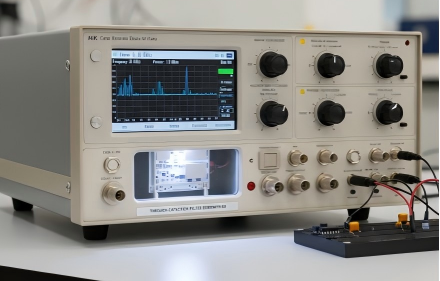
When a piece of mission-critical hardware fails electromagnetic compatibility (EMC) testing in the laboratory, the immediate instinct of many hardware engineers is to blame the electronic components. It is a common assumption that the electromagnetic interference filter is defective, underperforming, or that the supplier provided out-of-specification parts. However, in the vast majority of real-world B2B applications—from aerospace avionics to heavy industrial motor drives—the root cause of poor emi protection is rarely the component itself. Instead, the failure stems directly from how the component was physically and electrically integrated into the overall system architecture.
An EMI filter acts as a crucial barrier between noisy internal circuitry and the outside world. To perform its job properly, it relies entirely on optimal physical integration. Whether your design utilizes simple feed through capacitor components or a complex, heavy-duty power filter array, avoiding mechanical and layout pitfalls is absolutely essential. A passive emi filter is only as effective as the ground plane it is tied to and the shielding enclosure that surrounds it.
Through this comprehensive guide, we will explore the ten most frequent installation mistakes engineers make during assembly, the physics behind why these mistakes cause catastrophic EMC failures, and the actionable steps you can take to ensure your filtration system performs exactly as designed.
1. Mounting on Painted, Anodized, or Coated Surfaces
The fundamental effectiveness of any high-frequency filter depends on a low-impedance, highly conductive path to ground. A shockingly common assembly error is installing a filter onto a chassis panel that has been painted, anodized, or powder-coated. These coatings are excellent electrical insulators. When a filter is mounted over them, the high-frequency noise cannot sink into the chassis ground. Instead, the filter is electrically isolated, rendering it completely useless and sometimes even exacerbating the noise issue by acting as a resonator. Always mask mounting holes before painting to ensure a pristine, bare-metal contact patch [1].
2. Using Wire Leads for High-Frequency Grounding
High-frequency noise behaves very differently than direct current (DC). Engineers often mistakenly connect the ground terminal of a filter to the chassis using a length of copper wire. At high frequencies, even a short, one-inch piece of wire possesses significant parasitic inductance. This inductance creates high impedance, effectively blocking the high-frequency noise from reaching the ground. To resolve this, filters must be bolted or soldered directly to the metal bulkhead, achieving a 360-degree, zero-lead-length ground connection [2].
3. Ignoring Galvanic Corrosion Principles
In harsh or humid environments, mating dissimilar metals can lead to rapid galvanic corrosion over time. For example, mating a silver-plated filter directly against a raw, untreated aluminum chassis in a maritime environment will cause accelerated oxidation. This invisible oxide layer drastically increases ground resistance over months or years of service, leading to a delayed degradation of emi protection. Always consult anodic index charts and ensure your emi filter manufacturer provides compatible plating options (such as tin, nickel, or gold) tailored for your specific chassis material.
4. Over-Torquing the Mounting Nut
Threaded filters are physically robust, but the internal ceramic capacitor elements are inherently brittle. A frequent assembly line mistake is using uncalibrated pneumatic tools to tighten the mounting nut. Applying excessive torque physically crushes or micro-fractures the internal barium titanate ceramic structure. This can lead to an immediate short circuit, or worse, a latent defect that passes initial factory testing but fails catastrophically in the field under thermal or vibrational stress. Always use a calibrated torque wrench and adhere strictly to the manufacturer’s maximum torque specifications.
If the component shows short circuit, leakage current or other signs of permanent electrical failure after installation, the issue may no longer be limited to installation quality. See our Feedthrough Capacitor Failure Analysis guide for common component-level failure modes and root-cause investigation methods.
5. Applying Excessive Heat During Soldering
When installing solder-in filters, rigorous thermal management is critical. Dwelling too long with a high-wattage soldering iron can melt the internal solder joints that connect the ceramic capacitor to the center conductor pin. Furthermore, in high-reliability components, aggressive thermal shock can shatter the delicate glass-to-metal seal, destroying the hermeticity and allowing moisture ingress. Engineers should employ tightly controlled temperature profiles, utilize pre-heating plates for the chassis, and use precise induction or localized soldering techniques.
6. Mismatched Thermal Expansion (CTE)
Electronic enclosures often undergo extreme temperature fluctuations in aerospace or automotive applications. If a standard component is rigidly potted in a hard epoxy resin within a metal casing, the differing Coefficients of Thermal Expansion (CTE) between the epoxy, the metal, and the ceramic will generate massive internal mechanical shear stress. Over hundreds of thermal cycles, this stress will literally shear the capacitor in half. Always specify flexible potting compounds or procure ruggedized components specifically engineered for extreme thermal cycling.
7. Input and Output Cable Crosstalk
Even a perfectly mounted passive emi filter will fail if the system’s wiring layout defeats its purpose. A classic layout mistake is bundling the unfiltered, “noisy” input wires directly alongside the filtered, “clean” output wires using the same zip ties. High-frequency electromagnetic noise will simply couple across the air gap from the noisy wires to the clean wires via parasitic capacitance, completely bypassing the internal filter circuit. Input and output harnesses must be physically separated and, ideally, shielded from one another within the enclosure.
8. Placing the Filter Too Far from the Enclosure Boundary
An electromagnetic interference filter must be installed exactly at the point where the cable penetrates the shielded enclosure (the Faraday cage). If the filter is mounted deep inside the chassis on a printed circuit board (PCB), the unshielded length of cable running from the chassis wall to the filter will act as a broadcasting antenna. It will radiate noise into the internal cavity before the offending signal even reaches the filter. Bulkhead mounting is the only mathematically sound way to maintain the integrity of the electromagnetic shield.
9. Ignoring Impedance Mismatch Rules
A filter is not a one-size-fits-all component. Using a standard C-circuit filter in a circuit with low source and low load impedance is highly inefficient. Filter topologies (C, L, Pi, or T configurations) must be matched inversely to the system’s impedance to maximize insertion loss. Hardware engineers must utilize proper design guidelines to ensure the internal configuration of the filter actively opposes the impedance of the line it is protecting [3].
10. Inadequate Voltage and Current Derating
Finally, utilizing a standard component near its absolute maximum voltage or current rating in a high-temperature environment is a recipe for rapid dielectric breakdown. High-frequency ripple currents generate internal heat within the capacitor due to its Equivalent Series Resistance (ESR). If the component is not properly derated for the ambient temperature and operating frequency, it will experience thermal runaway and fail. Always consult the detailed derating curves provided by reliable manufacturers before finalizing your Bill of Materials.
Conclusion
Achieving electromagnetic compatibility is a complex, system-level challenge. A high-performance suppression component is only as good as the physical environment it is installed in. By ensuring pristine, bare-metal grounding, carefully managing mechanical torque, controlling soldering temperatures, and meticulously isolating cable routing, engineers can maximize the efficiency and lifespan of their suppression hardware. Avoiding these ten common installation mistakes prevents costly late-stage hardware redesigns, prevents assembly line scrap, and drastically accelerates your path to market and EMC certification.
Related technical guide: Feedthrough Capacitor Failure Analysis
Frequently Asked Questions (FAQ)
Q: Can I use conductive paint to fix a poorly grounded EMI filter?
A: Conductive paint is a poor substitute for direct metal-to-metal contact. It often degrades over time, flakes off under vibration, and introduces unacceptable impedance for high-frequency RF filtering, ultimately compromising your emi protection over the product’s lifespan.
Q: Why does my feedthrough capacitor show a short circuit right after installation?
A: This is almost always caused by mechanical stress. Over-torquing the mounting nut or forcefully bending the terminal pin during wire attachment can fracture the brittle ceramic capacitor inside, causing the internal conductive plates to short together permanently.
Q: How do I know the correct torque limit for my threaded EMI filter?
A: A premium manufacturer will list the maximum installation torque directly on the product datasheet. Never exceed this specified value and always use the supplied internal-tooth lock washers to ensure the nut does not vibrate loose in the field.
Need Help with Glass-to-Metal Sealed Miniature RF EMI Filters for Your Mission-Critical System?
Every aerospace and defense application is different — and so is every reliability challenge.
LCA’s engineering team can help you understand hermetic sealing, RF performance, and qualification requirements — and recommend the right glass-to-metal sealed miniature RF EMI filter for your specific needs.
Contact LCA today for one-to-one technical support and customized EMI suppression recommendations.
References:
[1] IEEE Electromagnetic Compatibility Society. “Grounding and Bounding Guidelines for EMC.”
[2] MIL-STD-461G. “Requirements for the Control of Electromagnetic Interference Characteristics of Subsystems and Equipment.”
[3] CISPR TR 16-3. “Specification for radio disturbance and immunity measuring apparatus and methods.”