INTRODUCTION
A miniature RF EMI filter is a small passive component that attenuates unwanted RF energy on a signal or power line within a defined frequency band. Its size makes it practical for radio, communication, and high-speed digital assemblies where board space is limited. Its performance, however, depends on test conditions, parasitic inductance, grounding, and installation, so a nominal frequency or package size is not sufficient for specification. This article explains the operating principle, the common topologies, and the parameters OEM engineers should confirm.
DEFINING A MINIATURE RF EMI FILTER
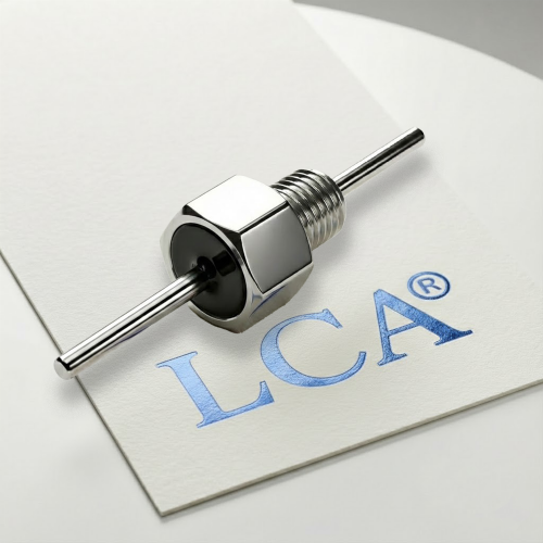
A miniature RF EMI filter is a compact, low-inductance passive device, often feedthrough or three-terminal in construction, placed where a conductor enters a shielded boundary or a sensitive RF circuit. The term “miniature” refers to package size, typically measured in millimeters, rather than to a specific performance class.
It does not, by itself, establish EMC compliance. It is one element of a filtering and shielding strategy.
HOW A MINIATURE RF EMI FILTER WORKS
The operating principle rests on the frequency behavior of capacitors and inductors:
- A capacitor presents impedance Z_C = 1 / (2πfC), which decreases as frequency rises. It shunts high-frequency noise to ground.
- An inductor presents impedance Z_L = 2πfL, which increases with frequency. It impedes high-frequency current along the line.
- A feedthrough or three-terminal geometry shortens the bypass path, reducing parasitic inductance so the capacitor remains effective at RF.
Attenuation Versus Frequency
For simple filters, attenuation increases with the number of reactive elements. Manufacturers commonly describe each ideal reactive element as contributing roughly 20 dB per decade of insertion loss, so a three-element pi or T network produces a steeper cutoff than a single capacitor. Actual slopes deviate from ideal values because of parasitics and losses, and must be read from measured curves.
COMMON FILTER TYPES
| Topology | Structure | Typical Advantage | Typical Consideration |
| C (single capacitor) | Capacitor to ground | Simple, low cost | Limited attenuation |
| L-C | Inductor and capacitor | Broadband attenuation | Size and loss |
| Pi | C-L-C network | Steeper slope | Size and passband loss |
| T | L-C-L network | Steeper slope | Size and passband loss |
| Three-terminal capacitor | Input, output, dual ground | Low ESL at high frequency | Current and power limits |
| Feedthrough capacitor | Conductor through capacitive layer | Low inductance at boundary | Requires housing bonding |
KEY SPECIFICATIONS
| Specification | Why It Matters |
| Frequency range and insertion-loss curve | Defines where attenuation applies; test conditions must be stated |
| Cutoff frequency | Often defined at the 3 dB point on the insertion-loss curve |
| Attenuation slope | Determines how quickly suppression increases above cutoff |
| Impedance and return loss | Insertion loss depends on source and load impedance |
| Rated voltage and current | Must cover the application with derating margin |
| Power handling | Governs heating and reliability |
| Self-resonant frequency | Above it, the element no longer behaves as a capacitor; attenuation may degrade |
| ESL and ESR | Limit high-frequency performance and loss |
| Ground (flange or pad) impedance | Strongly affects high-frequency attenuation |
| Package, mounting, and environment | Determines installation and reliability |
Insertion loss is commonly measured in a 50 Ω system by comparing voltage with and without the filter inserted, following the test method stated in the datasheet (for example MIL-STD-220 for some products). Curves are meaningful only when impedance, fixture, and termination are stated.
LCA specializes in ceramic EMI/RFI filtering solutions, including customized feedthrough capacitor designs for industrial and electronic applications.
If you are developing an EMI filter assembly or replacing an existing component, share your mounting dimensions, electrical requirements, and application conditions with our technical team.
[Contact LCA for Technical Support]
FACTORS THAT AFFECT REAL-WORLD PERFORMANCE
Grounding and enclosure bonding. Attenuation depends on a low-impedance path to the reference. Paint, oxide, or poor contact at the flange or pad can dominate high-frequency results.
Parasitic inductance and layout. Lead length, trace geometry, and via placement add inductance that limits the effective band.
Source and load impedance mismatch. Insertion loss measured at 50 Ω may differ substantially in another impedance environment.
Coupling around the filter. Input and output lines routed close together can bypass the filter.
SOURCING AND SUBSTITUTION CHECKLIST
- Confirm exact part number, datasheet revision, and footprint.
- Align test conditions (impedance, fixture, termination, frequency range) before comparing insertion-loss curves.
- Confirm cutoff, self-resonant frequency, and slope against the noise spectrum.
- Confirm voltage, current, and power ratings with temperature derating.
- Confirm grounding interface and mounting requirements.
- Document substitution review at both filter and system level.
Frequently Asked Questions
Q: What is a miniature RF EMI filter?
A small passive filter that attenuates unwanted RF energy on a signal or power line within a defined band.
Q: How does a pi filter work?
It places shunt capacitors at each end of a series inductor. The capacitors shunt high-frequency noise to ground, and the inductor impedes it along the line, giving steeper attenuation than a single capacitor.
Q: Why do insertion-loss values differ between datasheets?
Test impedance, fixture, termination, and frequency range differ. Compare only curves measured under equivalent conditions.
Q: Does a miniature RF EMI filter guarantee EMC compliance?
No. Compliance depends on the complete product, layout, grounding, cabling, and verification against the applicable standard.
Q: What should I request from a supplier?
Insertion-loss and return-loss data with test conditions, cutoff and self-resonant frequency, power and voltage ratings, footprint drawing, and environmental and certification documents.