Threaded EMI filters are a category of feedthrough-style electromagnetic interference suppression components used where shielded enclosures, panel walls, or chassis require a controlled entry point for electrical conductors. This guide covers how they work, how to select them, and what engineers and procurement teams need to verify before specifying a part.
A threaded EMI filter is a panel-mount electromagnetic interference suppression component designed to reduce conducted noise at chassis or enclosure entry points. Unlike PCB-mounted filters, threaded EMI filters bond directly to the metal enclosure through a threaded body, creating a low-impedance grounding path that improves EMC performance in industrial, aerospace, communications, and power systems.
What Is a Threaded EMI Filter?
A threaded EMI filter — also referred to as a feedthrough EMI filter or threaded feedthrough filter — mounts through a panel opening using a threaded body, typically secured with a nut and washer. The conductor passes through the component, which simultaneously carries current and routes high-frequency noise to the chassis ground through an internal capacitive or reactive network.
The word “threaded” describes the mechanical installation method, not a single electrical topology. Depending on the product series, the internal network may be a C-type (capacitor only), L-C, T, or Pi configuration. This matters in practice: two threaded EMI filters with the same thread size may perform very differently across frequency. In addition, PCB-Mount and Panel-Mount Filters feature distinct characteristics.
How It Differs from PCB-Mount and Panel-Mount Filter Types
PCB-mount EMI filters are soldered to a circuit board and rely on board-level ground planes for noise return paths. A threaded feedthrough filter, by contrast, bonds directly to the metal enclosure wall. This shorter, lower-impedance ground path makes it more effective at suppressing high-frequency conducted noise at the point of panel entry — before interference can propagate inside the enclosure.
How Does a Threaded EMI Filter Work?
The core mechanism is a shunt capacitor (or reactive network) connected between the signal or power conductor and the chassis ground. As conducted electromagnetic noise travels along the wire, the capacitive element presents a low-impedance path to ground at high frequencies, diverting the noise before it enters or exits the shielded enclosure.(Figure 1)
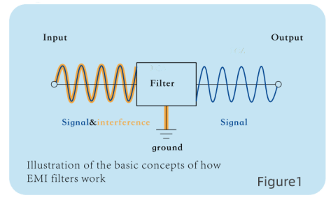
Common Mode vs. Differential Mode Noise
Conducted EMI appears in two forms. Common mode noise rides on both conductors simultaneously relative to ground; differential mode noise exists between the two conductors. A simple C-type threaded filter addresses common mode noise effectively. More complex topologies — L-C, T, or Pi — are used to mismatch highly varying source and load impedances, providing higher insertion loss for common mode noise across a wider frequency range.
Understanding which noise type dominates in your circuit is a prerequisite for selecting the correct topology. Misidentifying the noise type is one of the most common reasons a filter fails to meet EMC test requirements.
Insertion Loss and What It Actually Means
Insertion loss, expressed in dB, describes how much a filter attenuates noise at a given frequency. Higher insertion loss values indicate stronger attenuation. Some manufacturer datasheets report values such as 70 dB at 100 MHz or 1 GHz — but these figures are measured under specific impedance conditions (typically a 50Ω test circuit) and may not reflect performance in your actual installation.
Insertion loss is frequency-dependent, installation-dependent, and impedance-dependent. A figure from one datasheet cannot be directly compared to another unless test conditions are identical.
Types of Threaded EMI Filters
By Internal Circuit Topology
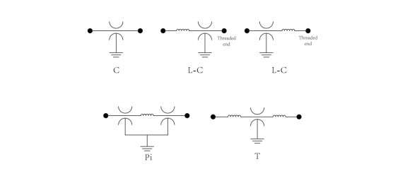
| Topology | Components | Noise Addressed | Source Impedance&Load Impedance |
| C-type | Single shunt capacitor | Common mode | High Source / High Load |
| L-C type | Series inductor + shunt cap | Common + some differential | Low Source / High Load |
| T-type | Two inductors + shunt cap | Common + differential | Low Source / Low Load |
| Pi-type | Two shunt caps + series inductor | Common + differential, broad BW | High Source / High Load |
Pi-type filters generally offer the broadest suppression bandwidth but also the most complex impedance behavior. Choosing a topology requires matching the filter’s characteristics to the actual noise profile of the circuit.
By Thread Size
Thread dimensions vary by manufacturer and target market. Metric threads (M3, M5, M8 and others) are common in European and Asian industrial equipment. UNC threads — for example, 6-32 UNC — are typical in North American applications. Confirm the thread specification against your panel design before ordering.
By Dielectric Material
Capacitor dielectric affects temperature stability and capacitance behavior:
- C0G (NP0): Highly stable across temperature; suitable for precision signal applications
- X7R: Good stability to ±15% over −55°C to +125°C; common for general-purpose filtering
- Z5U / Y5V: Not recommended for EMI filter applications due to high capacitance variation with temperature and DC bias
Key Specifications to Evaluate
When reviewing a datasheet or requesting a quote, the following parameters require explicit verification for each part number — they are not universal across a “threaded EMI filter” category:
| Parameter | Typical Range (varies by series) | Notes |
| Capacitance | 5 pF to 1.4 µF | Product-family specific |
| Working voltage | 50 Vdc to 1000 Vdc | Must match application |
| Current rating | Up to 25 A (some series) | Derate for temperature |
| Insertion loss | Up to 70 dB @ 100 MHz (select series) | Condition-dependent |
| Operating temperature | −55°C to +125°C (typical industrial grade) | Confirm with datasheet |
| Thread standard | Metric (M2.5–M10) or UNC (e.g., 6-32) | Match panel design |
Five-Step Selection Process for OEM Engineers
Step 1 — Characterize the noise. Determine the frequency range and mode (common or differential) of the conducted interference. This is best done with a spectrum analyzer or conducted emissions scan. Do not select a filter topology before this step.
Step 2 — Define required insertion loss. Based on the gap between your current emissions profile and the applicable limit (CISPR 32, EN 55032, or similar), determine the minimum attenuation needed at each critical frequency.
Step 3 — Confirm electrical ratings. Match the filter’s rated voltage and current to the actual operating conditions, with margin for transients and derating at elevated temperatures.
Step 4 — Select thread size and installation method. Confirm that the thread dimensions, panel thickness, and required torque spec are compatible with your enclosure design. Inadequate torque or poor metal-to-metal contact at the mounting interface can reduce effective grounding and degrade filter performance significantly.
Step 5 — Verify certification and compliance. Identify which standards apply to your end product and confirm the filter carries the appropriate marks. Passing a component-level certification does not guarantee system-level EMC compliance — the filter must be validated in the actual installation.
Certifications and Applicable Standards
The applicable standard depends on the intended use of the equipment, not just the component. The most relevant standards for threaded EMI filters are:
| Standard | Scope | Market |
| IEC 60939-3 | Passive filter units for EMI suppression; up to 1000 V AC / 1500 V DC | International |
| MIL-PRF-15733 | Performance spec for military/hermetic feedthrough filters and assemblies | Defense / aerospace |
| RoHS / REACH | Substance restriction compliance | EU & global supply chains |
Installation: What Affects Performance in Practice
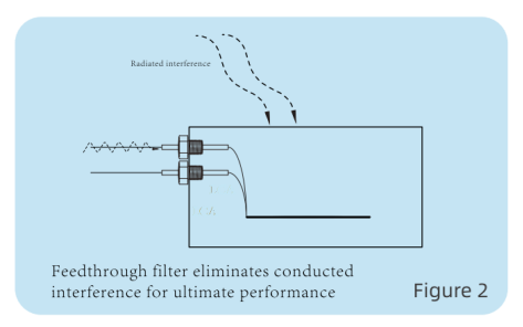
Threaded EMI filters depend on direct, low-impedance contact between the filter body and the chassis wall. Installation quality has a direct effect on effective insertion loss.(Figure 2)
Key installation factors:
- Torque value:Apply the torque specified in the manufacturer’s installation guidance. Under-torque reduces contact pressure; over-torque can damage the component or panel.
- Contact surface:Contact surface: Remove paint, anodizing, or corrosion around the entire circumference of the mounting hole to ensure a 360-degree, low-RF-impedance metal-to-metal bond. Avoid partial grounding which allows high-frequency noise leakage.
- Washer and nut stack-up:Use the washer type recommended for the specific product. Incorrect stack-up can create impedance in the ground path.
- Lead dress:Keep the leads on both sides of the filter as short as practical. Long leads on either side can re-couple noise around the filter.
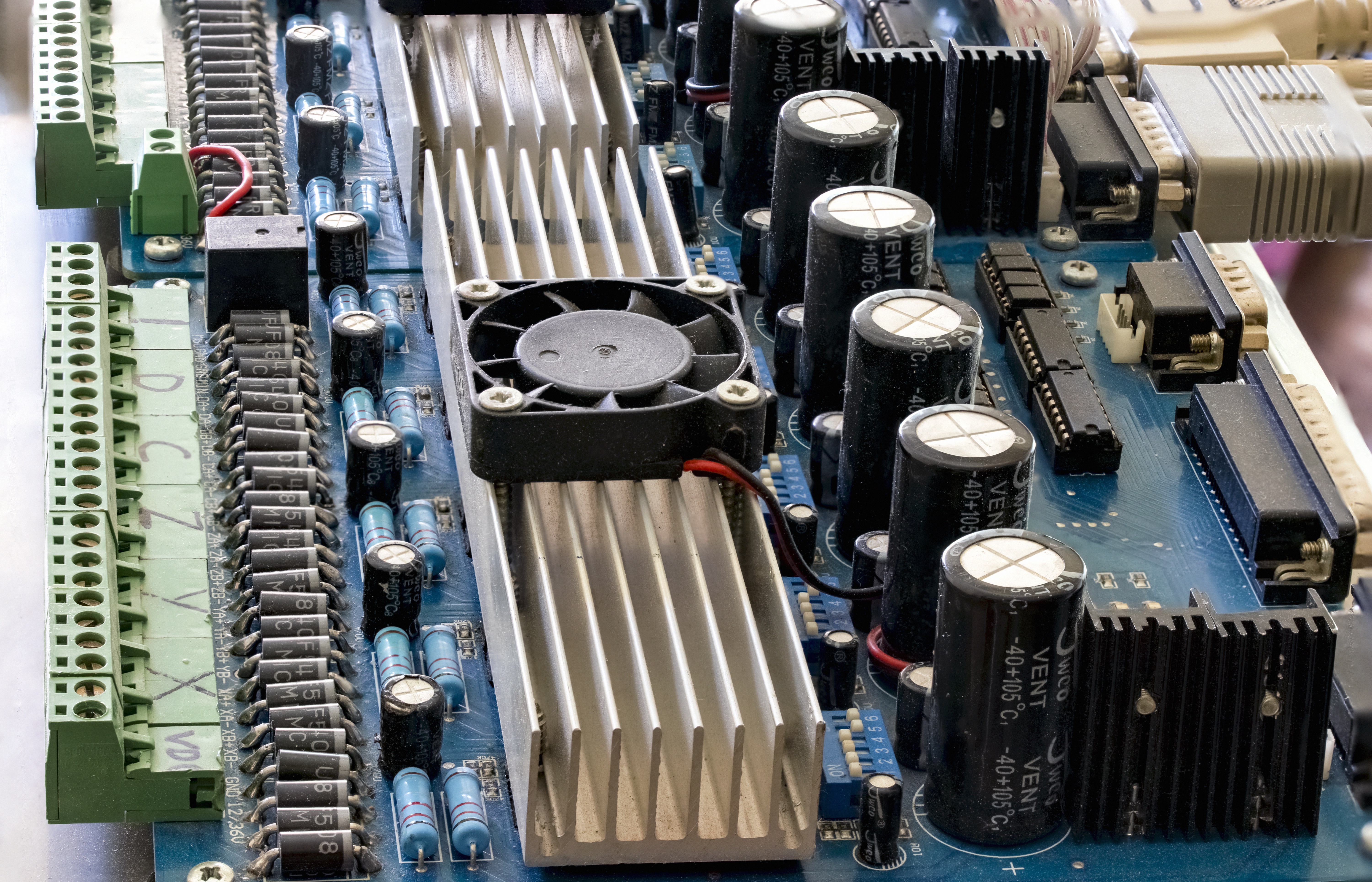
Typical Industrial Application Areas
Threaded EMI filters are used in applications where chassis shielding must be maintained at wire entry points:
- Industrial automation:PLC cabinets, servo drives, motor control enclosures, and I/O interfaces
- Communications equipment:RF chassis, transmitter/receiver units, and signal conditioning modules
- Aerospace and defense:Avionics enclosures and military equipment built to MIL-PRF-15733 or MIL-STD-461
- Power entry points:Higher-voltage or higher-current panel entries where conducted noise control is required within rated limits
- Harsh-environment equipment:Where hermetically sealed or resin-filled filter bodies provide protection against moisture, dust, vibration, and thermal cycling
Frequently Asked Questions
Q: Is a threaded EMI filter the same as a feedthrough capacitor?
Not exactly. A feedthrough capacitor is a basic C-type EMI filter, while threaded EMI filters may use C, LC, Pi, or T filter networks for different levels of noise suppression. The term “threaded” refers to the mounting method, not the internal filter design.
Q: Can I compare insertion loss numbers from different manufacturers?
Not directly. Insertion loss measurements depend on test frequency, the impedance environment (typically 50Ω in standard test setups), cable routing, grounding quality, and installation method. Values quoted by different manufacturers are only comparable when measured under identical conditions.
Q: Does a higher capacitance value always mean better filtering?
No. Higher capacitance shifts the filter’s effective frequency range lower. For high-speed digital or RF signal lines, a large capacitance value can degrade signal integrity. The appropriate capacitance depends on both the noise frequency and the signal’s bandwidth requirements.
Q: Will installing a threaded EMI filter guarantee I pass EMC testing?
No. Component-level certification does not guarantee system-level compliance. The filter must be validated in the actual enclosure, with the actual wiring harness and grounding configuration.
Q: What thread size should I specify?
Thread size depends on your panel design, current rating, and mechanical requirements. Metric threads (M3, M5, M8) are standard in European and Asian designs; UNC threads (such as 6-32) are common in North American equipment. Confirm compatibility before finalizing the design.
References
[1]IEC 60939-3:2024 — Passive filter units for electromagnetic interference suppression. Core international standard for passive EMI filter units.
[2]UL 60939-3 / UL 1283 — North American certification routes for EMI filters; applicable scope differs by standard.
[3]MIL-PRF-15733 — Military performance specification for EMI/RFI feedthrough filters and related assemblies.landandmaritimeapps.
[4]TE Connectivity: EMI Filter Selection — Practical selection note covering performance sensitivity, leakage current, and installation variables.
[5]Knowles blog: Application and Installation Considerations for EMI Filters — Helpful for mounting and system integration guidance.
[6]Astrodyne TDI: EMI Filter Installation Best Practices — Practical field guidance on installation effects and system-level validation
Next Steps
If you are specifying a threaded EMI filter for a new design or procurement project, the most important step is to obtain insertion loss curves across the relevant frequency range for the specific part number under consideration — not just headline specifications.
Request a technical datasheet or application note from the manufacturer or authorized distributor for the specific part number and topology you are evaluating. For complex EMC requirements, consult with a qualified EMC engineer before finalizing the filter selection.
Need Help Choosing the Threaded EMI Filter?
Selecting the best threaded EMI filter for your application can be challenging, especially in high-frequency or mission-critical environments.
The LCA engineering team can provide:
- One-to-one EMI filter selection support
- Threaded EMI filterrecommendations based on your application
- High-frequency EMI suppression solutions
- Custom EMC/EMI filter design assistance
- Industrial, medical, aerospace, and RF filtering guidance
If you have any doubts about selecting the optimal feedthrough capacitor for your system, reach out to the LCA team for professional technical assistance and customized EMI filtering solution guidance.