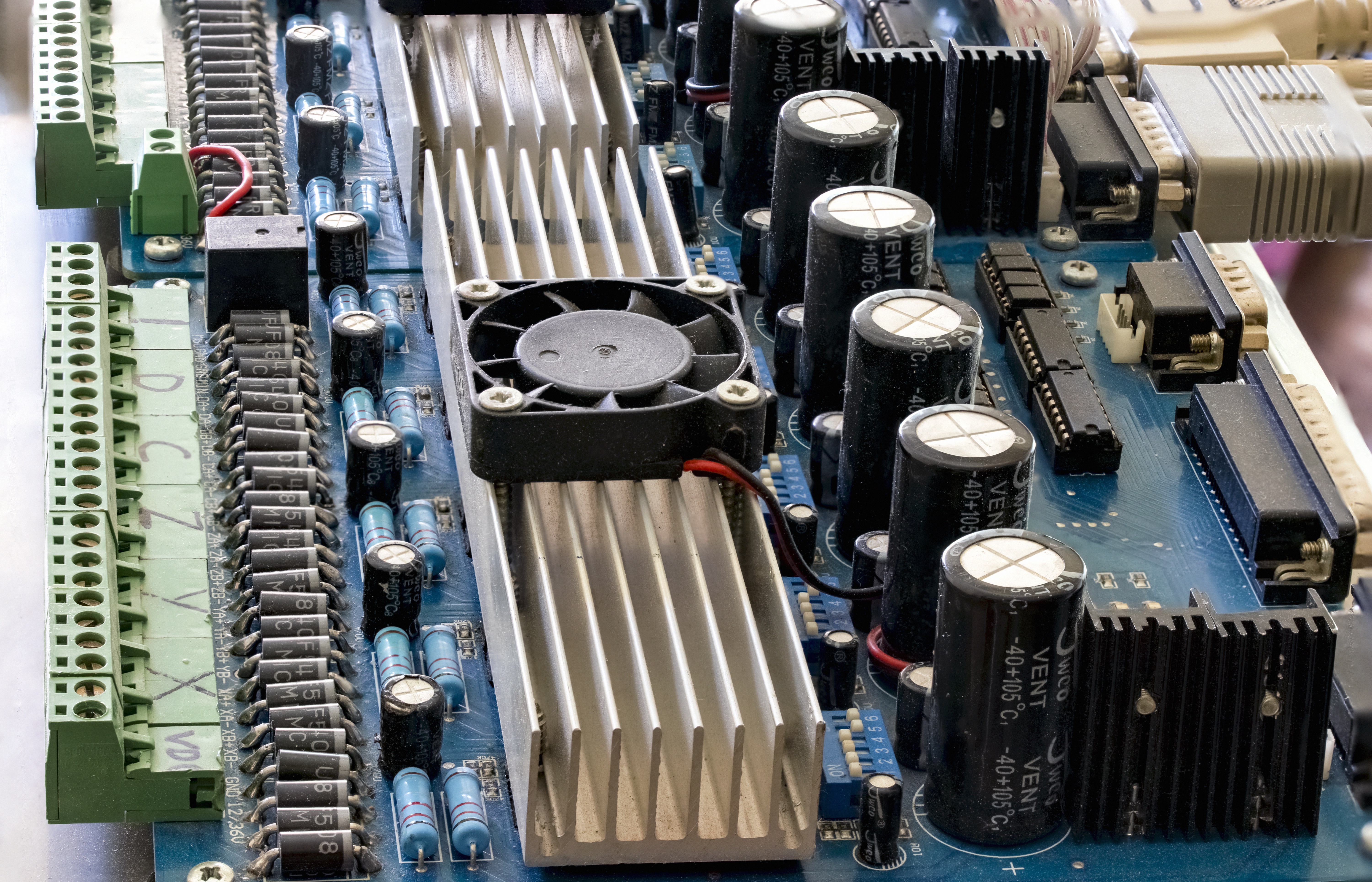
Electromagnetic interference (EMI) is one of the most common challenges in modern electronic systems. From industrial automation and medical equipment to aerospace electronics and communication systems, unwanted electrical noise can reduce system stability, interrupt signals, and create compliance problems.
One of the most effective solutions for high-frequency EMI suppression is the feedthrough capacitor.
A feedthrough capacitor is designed to filter unwanted high-frequency noise while allowing DC or low-frequency signals to pass through. Compared with standard capacitors, feedthrough capacitors provide much better insertion loss performance at high frequencies because of their special coaxial structure and low inductance design.
As electronic devices continue to operate at higher switching frequencies and faster data rates, choosing the correct feedthrough capacitor has become increasingly important for EMC compliance and system reliability.
What Is a Feedthrough Capacitor?
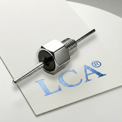
A feedthrough capacitor is a three-terminal capacitor designed specifically for EMI filtering applications. It is usually mounted through a metal panel or shielded enclosure, creating a low-impedance path for high-frequency noise to ground.
Unlike standard capacitors mounted on a PCB, feedthrough capacitors are optimized for:
- High-frequency EMI suppression
- Low inductance performance
- Improved insertion loss
- Better shielding effectiveness
- Reduced conducted emissions
They are commonly used in:
- EMI power line filters
- Medical equipment
- Aerospace electronics
- Military systems
- Industrial control systems
- RF communication devices
- Automotive electronics
According to research published in the IEEE Transactions on Electromagnetic Compatibility, feedthrough capacitors can significantly improve conducted EMI attenuation compared with standard bypass capacitors in high-frequency environments.
Key Factors When Choosing a Feedthrough Capacitor
1. Capacitance Value
The capacitance value directly affects the filtering frequency range.
General selection guidelines include:
- Low capacitance (10 pF – 1000 pF)
- Better for RF and ultra-high-frequency applications
- Minimal signal distortion
- Medium capacitance (0.001 µF – 0.1 µF)
- Common for industrial EMI suppression
- Suitable for power line filtering
- High capacitance (above 1 µF)
- Strong low-frequency noise suppression
- Often used in power supply applications
Choosing excessively large capacitance may increase leakage current or affect signal integrity, especially in communication systems and precision electronics.
2. Insertion Loss Performance
Insertion loss is one of the most important specifications in EMI filter design.
It measures how effectively the feedthrough capacitor attenuates unwanted noise across different frequencies.
Higher insertion loss generally means better EMI suppression.
Engineers should review insertion loss curves carefully and match them with the actual operating frequency range of the system.
For example:
- Switching power supplies often generate noise from 150 kHz to 30 MHz
- RF systems may require suppression above 1 GHz
- Automotive electronics often require broadband EMI filtering
International EMC standards such as CISPR 32 and MIL-STD-461 frequently reference conducted emission performance requirements for electronic equipment.
3. Voltage Rating
The voltage rating must always exceed the maximum operating voltage of the circuit.
Common voltage ratings include:
- 50 V
- 100 V
- 250 V
- 500 V
- 1000 V and above
For industrial and aerospace applications, engineers usually include additional safety margins to improve long-term reliability.
Using an underrated capacitor may result in dielectric breakdown, overheating, or premature failure.
4. Current Rating
Feedthrough capacitors used in power filtering applications must support the expected operating current.
Higher current systems generate additional heat, especially in compact enclosures.
Important considerations include:
- Thermal performance
- Ambient operating temperature
- Power dissipation
- Mechanical stability
Medical and aerospace systems often require components with stable performance under vibration and temperature variation.
5. Mounting Style and Mechanical Design
Feedthrough capacitors are available in different mounting configurations:
- Bulkhead mounting
- Solder mounting
- Threaded mounting
- PCB mounting
Proper enclosure bonding and grounding are critical for achieving effective EMI suppression.
Poor grounding can significantly reduce filter effectiveness, even when high-quality capacitors are used.
The shielding enclosure and feedthrough installation should form a continuous low-impedance grounding path.
6. Environmental and Industry Requirements
Different industries have different EMC requirements.
For example:
Medical Devices
Medical systems must comply with IEC 60601 EMC requirements and maintain extremely low leakage current.
Aerospace and Military Systems
Aerospace equipment often requires compliance with MIL-STD-461 and high-reliability environmental standards.
Industrial Equipment
Industrial automation systems typically focus on conducted emissions, surge resistance, and long-term durability.
Selecting certified and application-specific feedthrough capacitors can simplify compliance testing and improve system reliability.
Common Mistakes When Selecting Feedthrough Capacitors
Many EMI problems are caused not by component quality, but by incorrect selection or installation.
Common mistakes include:
- Selecting capacitance values based only on size
- Ignoring insertion loss data
- Poor grounding design
- Using standard capacitors instead of EMI-specific feedthrough capacitors
- Installing filters too far from the enclosure entry point
- Ignoring thermal performance
EMI suppression should always be considered as part of the complete system design rather than an isolated component choice.
Future Trends in EMI Filtering
As electronic systems become smaller and faster, EMI filtering technology continues to evolve.
Modern trends include:
- Miniaturized high-performance feedthrough capacitors
- High-frequency broadband suppression
- Low-leakage designs for medical electronics
- High-temperature materials for aerospace applications
- Integrated EMI filter modules
The growth of electric vehicles, renewable energy systems, AI hardware, and high-speed communication devices is also increasing global demand for advanced EMI suppression solutions.
Conclusion
Choosing the right feedthrough capacitor is essential for achieving reliable EMI suppression and EMC compliance.
Engineers should evaluate:
- Capacitance value
- Insertion loss
- Voltage and current ratings
- Mounting structure
- Environmental requirements
- Industry compliance standards
A properly selected feedthrough capacitor can significantly improve system stability, reduce conducted emissions, and enhance long-term product reliability.
As high-frequency electronics continue to expand across industrial, medical, aerospace, and communication sectors, feedthrough capacitors will remain a critical part of modern EMI filter design.
References
[1] IEEE Transactions on Electromagnetic Compatibility
[2] CISPR 32 Electromagnetic Compatibility Standard
[3] MIL-STD-461 Electromagnetic Interference Characteristics Requirements
[4] IEC 60601 Medical Electrical Equipment EMC Standard
[5] Henry W. Ott — Electromagnetic Compatibility Engineering
[6] Clayton R. Paul — Introduction to Electromagnetic Compatibility
Need Help Choosing the Right Feedthrough Capacitor?
Selecting the best feedthrough capacitor for your application can be challenging, especially in high-frequency or mission-critical environments.
The LCA engineering team can provide:
- One-to-one EMI filter selection support
- Feedthrough capacitor recommendations based on your application
- High-frequency EMI suppression solutions
- Custom EMC/EMI filter design assistance
- Industrial, medical, aerospace, and RF filtering guidance
If you are unsure which feedthrough capacitor is suitable for your system, contact the LCA team today for professional technical support and tailored EMI filtering recommendations.