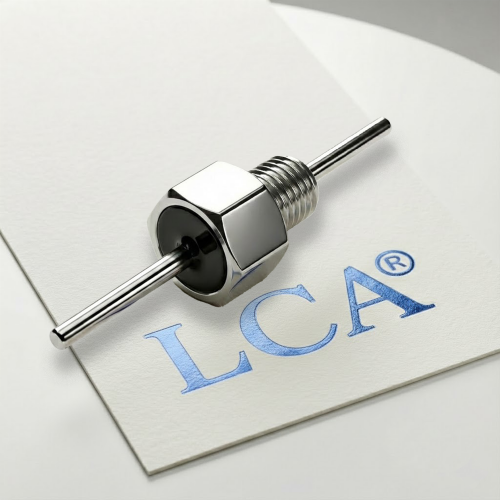
Tubular ceramic capacitors are used in RF power, high-voltage, and bypass circuits, but the tubular form does not guarantee reliability. Whether a part survives depends on the ceramic material, the electrodes and terminations, the encapsulation, the installation, and the electrical and environmental stress it sees. This article describes how these capacitors typically fail, how to separate component causes from application causes, and what evidence to ask suppliers for.
This article covers single-layer tubular ceramic capacitors. Much of the published failure-analysis literature addresses multilayer ceramic capacitors (MLCCs), so mechanisms drawn from that literature are noted as such. Treat them as indicative for tubular parts, not as direct equivalents.
Scope and Terminology
What “tubular ceramic capacitor” means here
A tubular ceramic capacitor uses a ceramic tube as the dielectric, with electrodes on the inner and outer walls. Terminations can be leads, mounting tabs, or screw connections. Vishay’s RF Power Tubular series, for example, uses single-layer Class 1 ceramic with mounting tabs and screw terminations for RF power use. A hollow body does not make a part a feed-through capacitor. If the internal connection is unclear, ask the supplier for the diagram.
Failure, parametric drift, and out-of-spec use
These three situations call for different responses:
- Component defect:the part fails within its rated conditions.
- Parametric drift:a parameter moves beyond its limit over time or under stress. Some drift is a material property. Class 2 dielectrics, for example, change capacitance with voltage, temperature, and time, and that behavior alone does not indicate a defect.
- Out-of-spec use:voltage, current, temperature, or mechanical load exceeds the rating.
Defining which case applies comes before any discussion of cause or responsibility.
Also distinguish failure mode (what is observed, such as an open or short) from failure mechanism (the physical process behind it, such as cracking or silver migration).
How Tubular Ceramic Capacitors Fail: Main Failure Modes
Failures in the research material commonly present as open circuit, short circuit, capacitance drift, reduced insulation resistance, increased leakage current, surface arcing, or mechanical cracking.
Dielectric breakdown and short circuit
Breakdown can follow overvoltage, transients, or local material defects. Heavily stressed thin-walled or small-volume ceramic parts with high local heating are more prone to burning or cracking, according to one failure-analysis source (Utmel). Voltage derating is a common countermeasure, but the appropriate margin should come from the manufacturer, not a general rule.
Cracking and mechanical damage
Ceramic is brittle. Bending, vibration, shock, thermal shock, and excessive mounting torque can cause cracks, terminal failure, or loss of seal. Cracks may not be obvious early and can lead to delayed failure, because moisture and silver migration can later develop within them. Much of the cracking literature concerns MLCC board flexure. For tubular parts with screw terminations or mounting tabs, torque and alignment are the more directly relevant installation factors.
Insulation resistance degradation and leakage
Reduced insulation resistance often appears before a short or breakdown, so it is a useful early indicator. Moisture, surface contamination, and electrode migration contribute. Rising leakage current can point to dielectric problems or surface contamination.
Capacitance drift and loss increase
Capacitance outside tolerance, or DF/Q outside limits, can come from aging, stress damage, or moisture. Higher dissipation factor produces more self-heating, which matters in RF service. Separate expected material behavior (especially Class 2) from damage-related drift.
Surface flashover, tracking, and partial discharge
At high voltage, surface condition, humidity, contamination, and encapsulation influence arcing. In semi-sealed ceramic capacitors in high humidity, dielectric breakdown and surface arc-over are reported as common problems (Utmel). Rated voltage alone is not sufficient. Installation and environment also matter.
Termination and solder joint failure
Loose terminals, detached leads, or poor joints can cause opens or intermittent faults. Some failure-analysis literature indicates that many ceramic capacitor failures originate in the external packaging that protects the capacitor element and lead assembly, and that electrical degradation and intermittent failures also occur.
Moisture-related degradation
High humidity can form a conductive film on the ceramic surface and promote silver migration, leading to leakage, arcing, or breakdown. Test claims about moisture resistance should state conditions rather than say “moisture resistant.”
Failure Causes: Component, Process, or Application?
| Category | Examples | Typical evidence |
| Material and manufacturing | Ceramic defects, wall-thickness variation, electrode or termination quality, incomplete sealing | Cross-section or DPA, lot comparison, process records |
| Assembly and installation | Excess torque, misalignment, soldering heat, mechanical stress on terminations | Crack location, torque records, installation review |
| Application and stress | Overvoltage, transients, excess RF current, self-heating, humidity | Operating waveforms, temperature data, field environment |
Do not attribute field failures uniformly to the customer or the component. A conclusion should follow from the evidence.
Evaluating Tubular Ceramic Capacitor Reliability?
Selecting a tubular ceramic capacitor for RF or high-voltage applications requires more than checking nominal capacitance and voltage. Operating waveform, RF current, temperature, humidity, mounting conditions, and termination design can all affect reliability.
For over 20 years, LCA has focused on EMI suppression solutions and electronic components, including ceramic feed-through capacitors and customized EMI suppression components.
Contact our team with your application requirements or relevant part number to discuss available product documentation and technical evaluation options.
Request Datasheets | Submit Your Specifications | Contact Technical Support
Stress Factors That Influence Reliability
Voltage and waveform. DC, AC, RF, and pulsed operation each stress the part differently. A DC rating should not be read as an equivalent RF or AC capability.
Temperature and self-heating. High temperature accelerates aging and lowers dielectric strength. Dissipation in RF service raises temperature further. Low DF or high Q reduces this heating, but does not remove the need for current-versus-frequency data and thermal checks.
Thermal cycling. Repeated temperature changes can stress the interface between ceramic and terminations because of thermal expansion mismatch.
Humidity and contamination. Humidity reduces surface insulation and can promote migration, particularly with silver electrodes.
Mechanical stress. Torque, vibration, shock, and mounting geometry affect cracking and terminal integrity.
Failure Mode, Likely Cause, and Prevention
| Failure mode | Likely causes | Preventive actions |
| Short circuit / breakdown | Overvoltage, transients, material defects, local heating | Apply manufacturer-recommended derating; confirm waveform; review lot data |
| Open circuit | Terminal or lead detachment, cracking, poor joint | Follow torque and soldering guidance; review termination drawings |
| Cracking | Mechanical load, thermal shock, torque, vibration | Check mounting geometry; control installation; assess thermal cycling |
| Low insulation resistance / leakage | Humidity, contamination, migration | Specify environment; request humidity test conditions; manage cleanliness |
| Surface arcing | High voltage, humidity, contaminated surface | Review clearances and encapsulation; verify in the installed configuration |
| Capacitance or loss drift | Aging, stress damage, dielectric class behavior | Request class-specific curves; separate normal drift from damage |
| Intermittent failure | Loose terminations, packaging damage | Inspect terminations; check mounting retention |
Conclusion
Tubular ceramic capacitors serve critical roles in RF power, high-voltage and bypass circuits, but their reliability depends heavily on material properties, construction, installation and operating conditions. Common failure modes include dielectric breakdown, cracking, reduced insulation resistance, leakage, surface flashover, parametric drift and intermittent connection faults.
Failures can stem from manufacturing defects, assembly errors or application-related stress. Voltage waveform, RF current, self-heating, thermal cycling, humidity, contamination and mechanical torque are key stress factors that accelerate degradation. It is essential to distinguish inherent dielectric behaviour, such as Class 2 capacitance drift, from damage-related failure, and to separate component-origin issues from improper usage through evidence-based root-cause analysis.
Reliability cannot be guaranteed by rated voltage and capacitance alone. Engineers must validate performance against the actual operating waveform, thermal profile, environmental conditions and mounting requirements. Proper derating, controlled installation, contamination management and supplier documentation review are foundational to reducing field failures.
Frequently Asked Questions
What are the most common failure modes of tubular ceramic capacitors?
Opens, shorts, capacitance drift, reduced insulation resistance, increased leakage, surface arcing, and cracking.
How do I tell a component failure from an application failure?
Compare operating conditions (voltage, waveform, current, temperature, installation) against the rating, then use failure analysis such as cross-sections and lot records.
Why do ceramic capacitors crack?
Brittle material combined with mechanical load, thermal shock, torque, or vibration. Cracks may stay hidden and cause delayed failure.
Does capacitance change mean the capacitor failed?
Not necessarily. Class 2 dielectrics change with voltage, temperature, and time. Compare against the datasheet curves and limits.
How does derating relate to reliability?
Lower stress generally slows degradation, but the appropriate margin should come from the manufacturer for the specific part and application.
Which reliability tests should I request?
Environmental, electrical, and mechanical tests relevant to your application, with documented conditions, sample sizes, and criteria.
What information supports a field failure investigation?
Lot number, installation conditions, operating waveform, failure symptoms, environment, and retained failed parts.