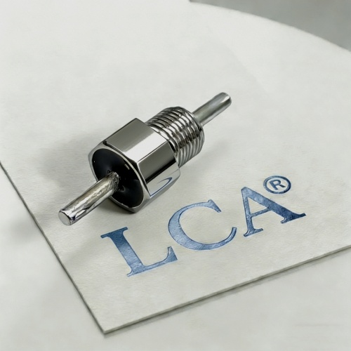
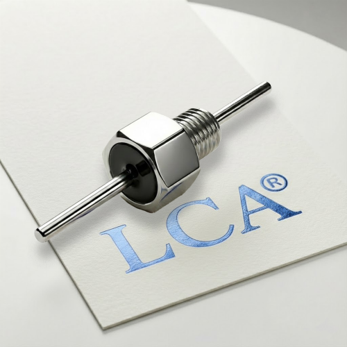
Two feedthrough filters can share the same capacitance and voltage rating and still not be interchangeable. Differences in thread, body length, grounding surface, topology, insertion loss under the same test conditions, sealing or qualification status can each cause a replacement to fail at assembly, in test or in service.
This guide is for OEM engineers who need to replace a feedthrough filter because of obsolescence, supply constraints or a second-source requirement. It sets out a step-by-step evaluation process and the evidence worth requesting. It does not provide tolerance rules or pass/fail thresholds, because those depend on your drawing, specification and application.
Quick Answer:
To identify a compatible feedthrough EMI filter replacement, compare the original and candidate parts across mechanical fit, electrical performance, environmental requirements and qualification status. Check the complete part number, drawing, mounting thread, body dimensions, filter topology, capacitance, voltage, current rating, insertion loss and hermeticity requirements. Supplier cross-reference information should be treated as a starting point rather than proof of interchangeability. Before approving a replacement, review supporting test data, evaluate samples in a representative assembly and complete any required engineering or customer approval.
When Do You Need a Feedthrough Filter Alternative?
A feedthrough EMI filter is a low-pass device mounted through a conductive chassis or bulkhead. It passes DC, power or low-frequency signals and shunts higher-frequency interference to the enclosure. Common reasons for looking at an alternative include:
| Trigger | Typical situation |
| Obsolescence | The original part is discontinued or has an end-of-life notice |
| Supply constraints | Lead time or availability puts the program at risk |
| Second source | A program or customer requires more than one qualified supplier |
| Cost or redesign | A change is considered for cost, or as part of a design update |
| Repair and service | A damaged or degraded filter must be replaced without reworking the bulkhead |
“Equivalent” and “interchangeable” are not the same. A cross-reference table, whether from a supplier or a distributor, is best treated as a candidate list. It generally does not establish form-fit-function equivalence, qualification status or installed EMC performance.
Step 1: Collect Baseline Information on the Original Part
Before comparing candidates, document what the original part actually has to do.
- Part identification:manufacturer, full part number including any suffix, revision, drawing, and for military-style parts the specification, slash sheet and dash number.
- Electrical data:topology, capacitance and tolerance, dielectric, rated voltage, rated current, DC resistance, insertion loss curve with its test conditions.
- Mechanical data:thread, flange, body dimensions, lead or pin geometry, plating, sealing method.
- Approval requirements:source control drawings, customer specifications, qualification level, and any approval needed for a substitution.
- Operating conditions:actual voltage, current, temperature range and the frequencies of concern. The application matters more than the catalog rating.
Suffix codes deserve particular attention. Some manufacturers use them to denote changes to pin length, body dimensions, threads, voltage, capacitance or test requirements, so a similar-looking base part number may not be the same part. Compare the complete ordering code and drawing.
Step 2: Compare Mechanical Compatibility (Form and Fit)
Match the original’s interface, not only its nominal thread size.
| Item | What to compare |
| Mounting style | Solder-in, screw-in, threaded, flange or panel mount; hole preparation and sealing hardware |
| Thread and flange | Thread specification, flange diameter, head shape |
| Body | Length, diameter and clearance on both sides of the panel |
| Center conductor or leads | Diameter, length, termination style |
| Plating and materials | Finish for solderability, corrosion resistance, bonding and contact resistance |
| Grounding contact | Mating surface, coating or paint on the panel, contact area |
| Hermetic or sealing method | Seal type and the sealing hardware used |
| Handling limits | Mounting torque, soldering and rework constraints |
Do not assume that all tin, tin-lead or gold finishes are interchangeable. Match or qualify the finish against your assembly and environmental requirements.
Torque limits are worth verifying as well. Excessive torque on threaded feedthrough parts can damage internal ceramic structures, and limits vary by product.
Looking for a Feedthrough EMI Filter Replacement?
Finding a suitable alternative involves more than matching capacitance, voltage or thread size. Mechanical dimensions, electrical performance, grounding, sealing and qualification requirements must also be considered.
LCA MIC has focused on EMI suppression components, including ceramic feedthrough capacitors and feedthrough EMI filter solutions for OEM applications.
If you are looking for a replacement for a discontinued filter, evaluating a second source or considering a customized solution, our team can review your available technical information to support preliminary product evaluation.
To start a comparison, please provide:
- Original manufacturer and complete part number
- Mechanical drawing or product datasheet
- Required capacitance, voltage and current ratings
- Insertion loss requirements and operating frequency range
- Environmental and hermeticity requirements, if applicable
[Submit Your Part Number for Technical Evaluation]
Step 3: Compare Electrical Compatibility (Function)
Build a side-by-side table that includes the test conditions behind every number.
| Parameter | Why it matters | Comparison note |
| Topology (C, L, Pi, T) | Different attenuation and impedance behavior | Replacing a C filter with a Pi filter changes attenuation, size and voltage drop and must be validated in the application |
| Capacitance and tolerance | Sets low-frequency shunt behavior; excessive capacitance can load bias or control circuits | Compare nominal value, tolerance, dielectric, DC-bias behavior and temperature coefficient |
| Dielectric type | C0G/NP0 and X7R behave differently over temperature and bias | Compare explicitly rather than assuming equivalence |
| Rated voltage and test voltage | Must cover normal, transient and test conditions | Check DC and AC ratings, dielectric withstanding voltage and derating |
| Rated current and DC resistance | Affects heating and voltage drop | Compare continuous current rating, DC resistance and temperature rise; assess any surge or inrush conditions your application imposes |
| Insertion loss vs. frequency | Primary performance metric | Compare at all critical frequencies, with the same test method, impedance and fixture |
| Insulation resistance and leakage | Relevant at high temperature and bias | Verify at the conditions you will actually use |
| Temperature range | Must cover mission and storage conditions | Check capacitance drift, leakage and insertion loss at extremes |
Compare Insertion Loss Under the Same Conditions
Insertion loss curves from different suppliers are comparable only if the measurement conditions match: method (for example MIL-STD-220 or CISPR 17), source and load impedance, fixture, load current, bias and temperature. Also check whether the values are typical or minimum. If conditions differ, ask for a retest under identical conditions or documentation of the differences.
Similar capacitance does not guarantee similar high-frequency attenuation. Dielectric, parasitic elements, construction and grounding all influence the curve. Bias, load current and temperature can also change the result, so a no-load room-temperature curve may not represent your operating point.
Step 4: Check Environmental, Reliability and Compliance Requirements
- Environment:temperature range, vibration, shock and corrosion exposure.
- Hermeticity:if the original is a hermetic part, confirm the seal type, the leak-rate requirement and the test method. “Hermetic” does not mean the same leak requirement in every document.
- Reliability and qualification level:for aerospace and defense programs, check whether QPL, QML, established reliability, traceability or customer approval applies. Verify status for the exact part, slash sheet and dash number rather than inferring it from a catalog page or a supplier statement.
- Material and substance declarations:RoHS, REACH or other declarations where your program requires them.
For MIL-PRF-28861 parts, the part number encodes the specification, slash sheet, dash number, case finish and product-assurance level. A replacement for such a part generally needs to meet the same slash sheet and dash number requirements unless the program formally approves a deviation. A commercial catalog part does not automatically satisfy a military specification or QPL requirement.
Step 5: Request the Right Evidence from the Supplier
Ask each candidate supplier for evidence you can review line by line.
- Datasheet and drawing for the candidate, including the complete ordering code.
- Insertion loss data under conditions identical to the original, or a clear statement of how the conditions differ.
- Test reports, certificates of conformance and lot traceability.
- Qualification evidence applicable to the specific part number, where relevant.
- A deviation list in which each requirement is marked “compliant,” “deviation” or “to be confirmed,” with the supporting document cited.
- Samples for evaluation and, where the supplier or production process is new, first article inspection to verify that the manufacturing process reproduces the qualified design.
A deviation list is useful because it makes differences explicit before they become assembly or test problems.
Step 6: Plan Validation and Change Control
Component-Level and System-Level Verification
Component data supports the decision, but installed performance depends on source and load impedance, grounding, layout, cable coupling and operating current and temperature. Whether a system-level EMC retest, or a risk-based regression test, is needed should be decided by engineering and by the program requirements. Purchasing should not decide this alone.
Installation quality also affects the outcome. Poor grounding, painted or nonconductive mounting surfaces, crossed input and output leads and long ground connections can reduce filtering performance regardless of which part is installed.
Approval and Documentation
| Step | Typical content | Typical owner |
| Candidate screening | Mechanical and electrical comparison, data review | Engineering with purchasing |
| Evidence collection | Test data, reports, qualification evidence | Purchasing with supplier |
| Verification | Sample evaluation, in-assembly testing where required | Engineering and test |
| Approval | Customer or program approval where the contract requires it | Program management, quality |
| Documentation | ECN or ECO, approved vendor list update, drawing changes | Configuration management |
| Ongoing control | Change notification for materials, process or construction | Purchasing, quality |
Agree in advance on change notification and on what triggers re-verification in future, such as a material, process or construction change.
Common Replacement Mistakes
| Mistake | Why it matters |
| Comparing only capacitance and rated voltage | Insertion loss, current, topology and mechanics also decide suitability |
| Assuming the same thread means the same fit | Head shape, flange, body length, lead length and torque limits may differ |
| Comparing curves measured under different conditions | The data is not comparable |
| Ignoring bias, current and temperature | The operating point may differ from the datasheet condition |
| Assuming a higher-voltage part is always safe | It does not guarantee equivalent capacitance, current rating or fit |
| Ignoring suffix codes | A similar base number may denote different dimensions or ratings |
| Treating a cross-reference table as approval | It identifies a candidate only |
| Skipping change control | Substitution may need ECN, AVL update or customer approval |
| Deciding on lead time or price first | Verification is postponed until the risk is already committed |
Frequently Asked Questions
How do I find an alternative for a discontinued feedthrough filter?
Collect the original part’s specification, drawing and actual operating conditions. Then compare candidates by mechanical fit, electrical function, environmental requirements and qualification status, and ask each supplier for data under conditions matching the original.
Can I replace a feedthrough filter if capacitance and voltage match?
Not by that alone. Topology, insertion loss, current, DC resistance, dimensions, sealing, plating and grounding conditions also need to match or be shown to be adequate.
What does “form, fit and function” mean for a filter replacement?
Form and fit relate to the physical and mounting interface. Function relates to electrical performance. For many programs, environmental and qualification requirements must be addressed as well.
Can I compare insertion loss curves from different suppliers?
Only if the method, impedance, fixture, bias, load and temperature are the same. Otherwise ask for a retest or a clear description of the differences.
Can a C-type feedthrough be replaced with a Pi-type filter?
Sometimes, but not automatically. A Pi filter may offer more attenuation, but it can change size, voltage drop and installed behavior, so it should be validated in the application.
Does replacing a filter require an EMC retest?
It depends on the application, the change and the program requirements. Installed performance depends on grounding, layout, cabling and impedance, so engineering should decide whether system-level or risk-based verification is needed.
Is a hermetic replacement automatically equivalent to the original?
No. Leak-rate requirements, construction and qualification status may differ, and they should be checked against the applicable specification.