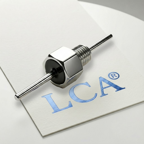
Press-in and solder-in EMI filters can feature identical electrical designs. However, their termination method impacts assembly yield, rework feasibility, mechanical stress on the ceramic element, and high-frequency performance after installation. For OEM engineers, mounting style is therefore a design and process decision, not merely a purchasing consideration.
This article compares both mounting methods, covers key installation and reliability factors, and provides a structured selection framework. It does not state that one method is universally superior. The optimal choice depends on your application, assembly workflow, and available validation data.
What is the difference between press-in and solder-in EMI filters?
Press-in EMI filters use a mechanical interference fit for installation, avoiding soldering heat but requiring precise hole dimensions, insertion force, and alignment. Solder-in EMI filters use solder joints for both electrical connection and mechanical retention, requiring controlled temperature profiles and proper soldering workmanship. The main differences involve installation stress, manufacturing processes, rework requirements, and reliability validation. Neither method is universally superior; the appropriate choice depends on the application, assembly process, and operating environment.
What Are Press-In and Solder-In EMI Filters?
Press-In EMI Filters
A press-in filter is retained by an interference fit. Depending on the product, the filter pin or body is pressed into a plated through-hole on a PCB or motherboard, or into a hole in a panel or chassis wall. No solder is used to make the connection. Some product families also offer threaded or other mechanical mounting options alongside press-in.
Solder-In EMI Filters
A solder-in filter is attached with solder, by reflow, wave or manual soldering, depending on the package. The solder joint provides both mechanical retention and the electrical connection. Feedthrough capacitor and filter manufacturers describe terminations (for example silver, copper or tin finishes) intended for solder attachment.
A Note on Scope: Board-Level vs. Chassis-Level Mounting
“Press-in” is used in two related contexts:
- Board-level press-fit:pins pressed into plated PCB holes.
- Chassis- or panel-level press-in:a feedthrough filter body pressed into a shield wall or bulkhead hole.
The design concerns differ. Board-level press-fit depends on hole size, plating, and board material. Chassis-level mounting depends heavily on the ground contact between the filter body and the wall. Confirm which context applies to your design before comparing datasheets.
Need Help Selecting the Right EMI Filter Mounting Method?
Choosing between press-in and solder-in EMI filters requires more than comparing installation methods. Mechanical dimensions, grounding requirements, thermal conditions, and high-frequency performance all need to be considered.
LCA MIC specializes in customized ceramic EMI feedthrough capacitors and miniature RF filters for industrial and RF applications.
Our team can help review your drawings, mounting requirements, and electrical specifications to identify suitable filter solutions.
- Custom mounting configurations
- Application-specific electrical specifications
- Technical drawing review
- Sample evaluation and engineering support
[Contact LCA MIC for Technical Support] | [Request a Quote]
Installation Differences
Press-In: Controlling Mechanical Stress
Press-in installation avoids soldering heat, but it introduces mechanical loads that need to be controlled:
- Hole specification:hole diameter, tolerance, plating and wall material all affect retention and contact quality. Follow the manufacturer’s installation drawing and any applicable press-fit standard for the interface.
- Insertion force and depth:excessive force or misalignment can damage the ceramic element, the terminations, or the hole.
- Tooling:supports and alignment fixtures are typically needed so that force is applied to the intended surfaces and not to the ceramic body.
Hole dimensions, press forces and limits must come from the specific datasheet or installation guide. They should not be inferred from general guidance.
Solder-In: Controlling Thermal Stress
Solder-in installation depends on a controlled thermal process:
- Temperature profile:peak temperature, ramp rate, time above liquidus and cooling rate all influence stress in the ceramic element and terminations. Lead-free processes generally impose higher thermal demands than tin-lead.
- Soldering method:reflow, wave and manual soldering expose the part to different thermal conditions. Direct iron contact with the ceramic body should be avoided.
- Workmanship criteria:joint acceptance is commonly assessed against IPC-A-610 and process requirements in J-STD-001, in addition to the filter manufacturer’s recommendations.
Rework and Replacement
Press-in connections are often described as easier to rework, since no solder is involved. This depends on the design. Repeated insertion can deform holes or terminations, and some manufacturers limit the number of insertions. Solder-in filters can be reworked, but the added heat cycle needs to stay within the part’s thermal limits, and rework is typically harder in dense assemblies. Check the supplier’s guidance on rework limits.
Engineering Considerations for Custom EMI Filter Installation
For customized EMI filter applications, mounting requirements should be considered during the initial design stage rather than after the electrical specifications have been finalized.
Factors such as mounting hole dimensions, thread specifications, terminal geometry, grounding interfaces, plating materials, and sealing requirements can affect both manufacturability and installed performance.
At LCA MIC, we recommend reviewing mechanical drawings and electrical requirements together when developing customized feedthrough capacitors and miniature RF EMI filters. This helps reduce potential integration issues during prototype evaluation and production qualification.
Reliability Differences
Reliability differences are mainly the result of installation process quality and the operating environment, not the termination type alone. The points below are the main considerations.
Grounding and High-Frequency Performance
For feedthrough and similar filters, the ground connection strongly affects high-frequency insertion loss. A filter with low internal inductance can still underperform if the ground path is long, narrow, or contaminated. Whichever method you use:
- Keep the ground path short and low in impedance.
- Make sure the contact surfaces are clean and free of paint or oxidation where metal-to-metal contact is intended.
- Keep input and output wiring separated, since coupling across the filter can bypass its attenuation.
Insertion loss on datasheets is usually measured per MIL-STD-220 in a 50 Ω system. Performance in your system, with different source and load impedances and your mounting conditions, may differ, so verify under installed conditions.
Thermal Stress
Ceramic capacitor elements are sensitive to thermal shock and uneven heating. Solder-in processes expose the part to heat, so profile control and handling matter. Press-in avoids soldering heat, which can be an advantage for thermally sensitive assemblies, although the assembly may still see other thermal exposure during the rest of the process.
Mechanical Stress, Vibration and Shock
- Press-in:retention depends on interference fit. Hole tolerance, plating condition and material properties affect long-term contact behavior. Evaluate performance under vibration, shock and thermal cycling if the environment is demanding.
- Solder-in:joint integrity depends on solder quality and the mechanical environment. Thermal cycling and vibration can fatigue joints, and board flex can transfer stress to the ceramic element.
Neither method is inherently immune to mechanical failure. Qualification data from conditions that resemble your application is the most reliable evidence.
Sealing and Environmental Protection
Environmental sealing and hermeticity are usually properties of the filter’s construction (for example glass-sealed or resin-sealed designs) and of how the filter is sealed to the housing, not of the termination method alone. For applications with moisture, contamination or pressure requirements, check the sealing specification and test method for the specific part and mounting arrangement.
Comparison Table
The table below is qualitative. Actual behavior depends on the product, process and application, so it should be read together with the manufacturer’s datasheet.
| Consideration | Press-In | Solder-In |
| Joint formation | Interference fit | Solder joint |
| Thermal exposure during installation | No soldering heat | Depends on reflow, wave or manual process |
| Main process risk | Insertion force, hole quality, alignment | Temperature profile, cooling rate, joint quality |
| Rework | Often possible; limits on re-insertion may apply | Possible; added heat cycle must be controlled |
| Process requirements | Hole tolerance, plating, tooling | Soldering equipment, profile control, inspection |
| Typical standards referenced | Press-fit and interface standards, manufacturer drawings | IPC-A-610, J-STD-001, manufacturer profiles |
| Key validation points | Retention, contact resistance, insertion loss as installed | Joint integrity, thermal cycling, insertion loss as installed |
| Sealing | Determined by filter construction and mounting design | Determined by filter construction and mounting design |
Common Mistakes When Switching Methods
- Comparing only insertion loss curves.Mounting and grounding conditions can shift installed performance.
- Treating the two methods as drop-in equivalents.Hole geometry, mounting surface, sealing and ground path may all differ, so a change generally calls for revalidation.
- Overlooking the thermal budget.Soldering profiles, especially lead-free, can exceed what a part tolerates if not controlled.
- Validating samples under conditions that differ from production.Hand-soldered or lab-pressed samples may not represent production assembly.
- Applying force or heat to the ceramic body.Both press tools and soldering irons can cause damage if misapplied.
Frequently Asked Questions
Do press-in and solder-in filters have the same electrical performance?
Not necessarily. The filter element may be similar, but installed performance depends on the ground connection, wiring layout and mounting conditions. Verify performance in the installed configuration.
Which method is more reliable?
Neither is reliable in all conditions. Results depend on process control, vibration, thermal cycling, and the quality of the specific design. Use test data representing your application.
Can I replace a solder-in filter with a press-in version?
Not without checking. Mounting geometry, hole requirements, ground path and sealing may differ, and the change typically needs engineering review and revalidation.
Can press-in filters be removed and reinstalled?
It depends on the design and the manufacturer’s limits. Repeated insertion may affect retention or contact quality, so follow supplier guidance.
Does soldering damage EMI filters?
It can if the thermal profile or handling is outside recommended limits. Ceramic elements are sensitive to thermal shock and mechanical stress, so follow the datasheet profile.
Is the sealing performance determined by the mounting method?
Mostly by the filter construction and how it is sealed to the housing, not by the termination type alone. Confirm the sealing specification and test method for the specific part.