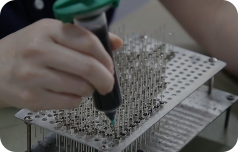
Feedthrough capacitor failure analysis helps engineers determine whether a problem is associated with electrical stress, environmental exposure, installation, aging or component quality.
When feedthrough capacitors malfunction in end equipment field operation, engineers usually default to judging defective components and submit replacement requests to component suppliers. In practice, the majority of field failures of feedthrough capacitors stem from insufficient application design margin rather than inherent manufacturing defects. Common overstress conditions include inadequate voltage derating, repeated thermal cycling, long-term moisture exposure and excessive mechanical shock & vibration. Distinguishing failures caused by component flaws and failures induced by insufficient design margin is essential to avoid repeated breakdowns and reasonably divide accountability between equipment designers and component manufacturers.
This guide details the most prevalent feedthrough capacitor failure modes, digs into their fundamental root causes, and delivers actionable identification and preventive countermeasures for each failure category.
What Causes Feedthrough Capacitor Failure?
A failed component should not be assigned to a single cause before the operating and installation conditions are reviewed. Most feedthrough capacitor field malfunctions originate from insufficient design safety margin against real operating stress. Manufacturing defects do exist, yet they mainly lead to infant mortality failures: breakdowns appear in the early service stage, hitting an entire batch or a concentrated subset of parts.
Sporadic, delayed failures emerging weeks, months or years after equipment deployment are almost always caused by inadequate design margin rather than production flaws. Such capacitors fully comply with official datasheet specifications when leaving the factory, yet the end system exposes them to operating stress exceeding the limits considered during design.
Common Feedthrough Capacitor Failure Modes & Root Cause Breakdown
Failure Mode 1: Dielectric Breakdown Under DC Bias
The failure mechanism: Applied DC voltage exceeds the dielectric’s withstand voltage threshold. The capacitor’s insulation resistance drops sharply, resulting in permanent short-circuit failure or drastically elevated leakage current.
Root cause: Insufficient DC voltage derating is the dominant trigger. X7R and other high-K ceramic dielectrics exhibit severe capacitance roll-off under DC bias. A component rated 1000 pF at 0 V DC may only retain 500–700 pF when operated at full rated voltage, subject to dielectric formulation and voltage ratio. If designers select capacitors based solely on zero-bias nominal capacitance without referencing derating curves, the real usable capacitance during operation falls below design requirements, raising electric field stress across the dielectric.
Failure Identification: Abrupt short circuit or excessive leakage current; damage is catastrophic and non-repairable. Visual signs such as charring or discoloration on the capacitor body often appear.
Prevention: Always Review official DC bias derating curves from the datasheet for all X7R and high-K dielectric feedthrough capacitors. Confirm the effective capacitance under maximum operating voltage meets circuit filtering demands. For applications requiring tight capacitance stability, C0G (NP0) dielectric delivers minimal capacitance shift, though its volumetric capacitance density is lower.
Failure Mode 2: Thermal Stress and Solder Joint Cracking
The failure mechanism: Repetitive thermal cycling generates cyclic mechanical fatigue on solder joints that bond feedthrough capacitors to PCBs. This fatigue originates from mismatched coefficients of thermal expansion (CTE) between the ceramic capacitor body and PCB substrate.
Root cause: Thermal mechanical stress accumulates over cycles, determined by both the temperature swing (ΔT) per cycle and total cycle count, rather than only maximum/minimum temperature limits. A capacitor that remains intact during static storage at -40 ℃ ~ +85 ℃ may develop cracked solder joints after merely 5 heating-cooling cycles between 25 ℃ and 60 ℃. Periodic temperature fluctuation creates recurring stress that accumulates over time.
Failure Identification: Intermittent circuit malfunctions or slow, progressive performance degradation after thermal cycling tests. Fault occurrence is temperature-dependent; failures only emerge when the component reaches a specific temperature range that opens microcracks inside solder joints.
Prevention: Optimize thermal cycling durability via proper component selection and refined PCB layout. Place thermally sensitive feedthrough capacitors away from large PCB edges, where CTE-induced deformation reaches peak levels. For high-reliability mission-critical equipment, perform thermal cycling reliability testing matching the actual end-use operating environment.
Failure Mode 3: Moisture Ingress and Corrosion in Resin-Sealed Capacitors
The failure mechanism: Water vapor slowly diffuses through the resin encapsulation over long-term operation and reaches internal metal electrodes, triggering electrochemical corrosion. Corrosion of silver or nickel electrode plating elevates leakage current continuously and may eventually create an open circuit.
Root cause: Resin encapsulation cannot deliver true hermetic sealing; the polymer material permits gradual moisture diffusion. Even capacitors passing standard humidity-bias qualification (85°C / 85% RH, 500–1000 hours) will suffer cumulative moisture ingress after several years of field operation. The risk spikes for equipment with non-sealed housings or systems exposed to recurring condensation.
Failure Identification: Slow, continuous leakage current growth, capacitance drift, or unstable intermittent filtering performance. This failure mode is delayed: no obvious defects appear within the first year of operation, while degradation surfaces after 3–5 years of service.
Prevention: Specify hermetic glass-to-metal sealed feedthrough capacitors for high-humidity equipment or products requiring multi-year long-term reliability. Resin encapsulation offers cost advantages for low-stress applications, but reliability must be validated via extended humidity-bias testing or field trial under representative working environments.
Failure Mode 4: Vibration and Mechanical Shock
The failure mechanism: External vibration whose frequency matches the component’s natural resonant frequency triggers violent mechanical oscillation. The cyclic stress fatigues solder joints and may fracture internal bonding structures inside the feedthrough capacitor.
Root cause: Insufficient mechanical fixation and mounting design for high-vibration operating environments, including military vehicles, aerospace equipment and heavy industrial machinery. Recurring displacement and bending of the capacitor under vibration build up irreversible fatigue damage.
Failure Identification: Intermittent malfunctions that only appear under specific vibration frequencies where resonance occurs; no failure symptoms at other vibration magnitudes. This behavior is frequently misdiagnosed as an electrical circuit defect due to its unstable, intermittent nature.
Prevention: Select feedthrough capacitors qualified to meet required vibration standards such as MIL-STD-810 for dynamic environments. Optimize component layout and mounting structures to cut mechanical stress. Add potting compound or full encapsulation to damp resonant movement of the assembly.
Failure Mode 5: Parametric Drift and Aging Over Time
The failure mechanism: Key electrical specifications of feedthrough capacitors (capacitance, leakage current) shift slowly over years driven by inherent ceramic dielectric aging. This gradual drift is a natural material characteristic rather than a manufacturing defect, and external operating stress speeds up degradation.
Root cause: Slow microscopic reactions accumulate throughout service life: dielectric polarization, electrode ion migration and chemical reactions at the ceramic-electrode boundary. Aging rate rises sharply with temperature; a capacitor exposed to 85 ℃ exhibits far more severe parametric drift than an identical unit stored at 25 ℃ over the same time span.
Failure Identification: Slow, continuous drift of capacitance or leakage current over months or years. All parameters meet specifications when the component is new, and deviation expands steadily as service time accumulates.
Prevention: For long-lifetime equipment, run accelerated aging testing to confirm electrical performance at end-of-life. Build sufficient design margin to accommodate predicted parametric shift over the full service cycle. Circuit design must rely on end-of-life electrical performance instead of nominal new-component characteristics.
Failure Mode 6: Manufacturing Defects — Incomplete Seals and Voids
The failure mechanism: Imperfections generated during sealing or assembly create conductive leakage paths for moisture penetration, or induce localized electric field concentration. As a result, the capacitor suffers dielectric breakdown under stress far below its rated specification.
Root cause: Defective sealing procedures (imperfect glass-to-metal seals, trapped voids inside resin encapsulation), insufficient in-line factory inspection, or mechanical damage generated during component handling and assembly.
Failure Identification: Typical infant mortality clustering: failures emerge within the early service stage, impacting an entire batch or a large share of units. After screening to remove these defective samples, the rest of the batch maintains stable long-term performance.
Prevention: Validate supplier quality systems by conducting sample testing including ESS environmental stress screening, humidity-bias aging and high-voltage withstand tests for every production batch. Demand formal test reports and full batch traceability records from your component supplier.
Distinguishing Design Margin Failures from Manufacturing Defects
| Characteristic | Design/Application Failure | Manufacturing Defect |
| Failure timing | Sporadic, delayed (weeks to years) | Infant mortality, early clustering |
| Lot impact | Affects multiple lots, random units | Affects entire lot or batch |
| Reproducibility | Reproducible under same stress conditions | Rarely reproducible; scattered pattern |
| Prior history | May see similar failures in earlier designs | Typically new or isolated to one supplier |
| Stress correlation | Failures correlate with environmental stress | Failures may occur at lower stress |
Root Cause Investigation Framework
When investigating a feedthrough capacitor failure, work through these questions:
When did the failure occur? Early-life failures suggest manufacturing defects. Mid-life or delayed failures suggest design-margin issues or aging.
What is the failure symptom? Open circuit, short circuit, parametric drift, or intermittent behavior? The symptom often points toward the failure mode.
In what environment did the failure occur? Temperature range, humidity, vibration level, voltage stress? Correlate the environment to known stress factors.
Is it one unit or multiple units? Single-unit failures are more likely design-margin or application-induced. Multiple units from the same lot suggest manufacturing problems.
Did previous designs have similar issues? If a similar product experienced the same failure, it reinforces the design-margin hypothesis. If this is the first time this failure has appeared, manufacturing or a new environmental stress is more likely.
Prevention Strategies
Design Margin Verification
Define and validate all electrical safety margins at the early design phase of your project:
Voltage derating: For X7R and other high-K ceramic feedthrough dielectrics, reserve sufficient voltage margin against dielectric breakdown. Maintain a minimum 1.5–2× safety factor relative to the component’s rated voltage.
Temperature derating: Validate capacitor electrical performance across the complete operating temperature range, accounting for component manufacturing tolerance to guarantee consistent circuit filtering performance.
DC bias derating: Refer to the manufacturer’s DC bias derating curve to calculate actual effective capacitance under maximum working voltage. Complete circuit design based on this de-rated capacitance value instead of the nominal zero-voltage capacitance rating.
Component Selection
C0G vs. X7R tradeoff: C0G / NPO dielectric delivers ultra-stable capacitance under wide temperature variation and DC bias, at the cost of lower volumetric capacitance density. X7R high-K dielectric provides much higher capacitance density but demands strict voltage derating to avoid performance degradation. Final selection must prioritize design margin requirements rather than only nominal capacitance value.
Sealing approach: For products requiring multi-year reliability under high humidity or fully sealed housing conditions, hermetic glass-to-metal sealing outperforms resin encapsulation in long-term protection, though it comes with a higher component cost.
Testing and Validation
Burn-in or ESS: Implement ESS matching real operating conditions to screen infant mortality defects from new production batches at the factory stage.
Accelerated life testing: Perform accelerated aging under elevated temperature and voltage to confirm sufficient design margin that maintains acceptable electrical performance at the defined end-of-life cycle.
Environmental validation: For equipment exposed to vibration, thermal cycling, high humidity or other unique stresses, complete validation testing replicating actual field operating conditions.
Summary: Failure Investigation Checklist
When investigating a feedthrough capacitor failure:
- Document failure timing (early, mid-life, end-of-life)
- Verify actual operating voltage, temperature, and environmental stress
- Check component datasheet: DC bias derating for your voltage level
- Verify design margin against rated specifications
- Determine whether the failure is isolated or affects entire lot
- Request supplier failure analysis and lot documentation
- Assess whether design, material, or installation changes are needed
- Validate corrective action through testing
Frequently Asked Questions
Q: Why did a capacitor fail if it meets the published specification? Meeting the published specification means the component performed within its rated limits when manufactured. It does not guarantee performance in your specific application if the application stresses the component beyond the design margin. Your circuit design must derate the component for your actual operating conditions.
Q: How much design margin do I need? This depends on the failure consequence and the application criticality. For non-critical applications, 1.5–2× safety factor on voltage is common. For mission-critical applications, 2–3× or higher may be appropriate. Use reliability standards or industry guidelines for your application domain.
Q: Should I always use hermetic sealing to avoid moisture failures? Hermetic sealing is more reliable for long-term moisture exposure, but it adds cost. For industrial applications with reasonable moisture exposure, resin sealing is often adequate. For aerospace, medical implant, or sealed-enclosure applications, hermetic is typically necessary. Validate for your specific application environment.
Q: How do I know if a failure is the component’s fault or my design’s fault? Evaluate the failure pattern and timing. Manufacturing defects typically cause infant mortality. Design-margin failures appear later and often correlate with environmental stress. Consult with the supplier for their failure analysis, and objectively assess whether your design provided adequate derating for the actual application stress.
Next Steps
Feedthrough capacitor failure can result from electrical stress, environmental exposure, installation damage, aging or component defects. A reliable root-cause investigation should compare the observed symptom with the operating conditions, assembly process, lot history and test evidence.
Preventive design should include suitable electrical margin, environmental validation, controlled installation and clear supplier documentation.
If you are investigating a feedthrough capacitor failure or designing for improved reliability, contact LCA’s application engineering team for guidance specific to your application.
Technical guidance in this article is based on general ceramic capacitor reliability principles. Specific failure modes, root causes, and prevention strategies are application- dependent. Failure analysis should be tailored to the actual observed failure pattern, operating conditions, and component parameters in your specific case. Consult component datasheets, reliability testing standards appropriate to your application domain, and supplier failure analysis data when investigating specific failures.