A feedthrough capacitor is a three-terminal capacitive component designed so that the signal or power conductor passes through the component body, with the capacitance connected between the through-conductor and an outer electrode that bonds to chassis or panel ground. This geometry is the defining feature of the component — and the reason it performs differently from a standard two-terminal capacitor in EMI filter applications.
In this article, LCA engineers walk you through what feedthrough capacitors are, why their geometry matters for high-frequency filtering, how they are constructed, how to select them, and where they are used.
The Core Problem: Why Standard Capacitors Lose Effectiveness at High Frequencies
Parasitic Inductance in Two-Terminal Capacitors
When a standard two-terminal capacitor is used as a shunt element to chassis ground, the noise current must travel from the line conductor into one terminal of the capacitor, pass through the capacitor body, exit from the other terminal, and travel along a ground trace or lead to the ground reference. This current path — including the leads, pads, and any ground trace — introduces equivalent series inductance (ESL).
At frequencies below the component’s self-resonant frequency (SRF), the capacitive impedance dominates and the shunt element works as intended. As frequency rises, the ESL becomes increasingly significant. At the SRF, the capacitive and inductive reactances cancel, the shunt impedance reaches a minimum, and attenuation is at its peak. Above the SRF, the inductive reactance dominates — the component behaves as an inductor, and its shunt impedance rises with frequency. At this point, the capacitor has stopped attenuating and may actually be providing a high-impedance path that allows noise to pass.
The Practical Consequence
Engineers who specify a capacitor by value alone, without verifying the SRF against the noise frequency, may be selecting a component that cannot perform the intended filtering function in the relevant frequency range. This is particularly common in designs where conducted noise extends into the tens or hundreds of MHz — a range frequently encountered in switching power supplies, motor drives, and high-speed digital interfaces.
What Is a Feedthrough Capacitor?
Definition and Geometry
A feedthrough capacitor is a three-terminal component where the line conductor passes through the body of the component. One terminal is the input end of the through-conductor; one is the output end; and one — typically the outer electrode or mounting body — connects to chassis or panel ground. In some constructions, the outer electrode is the mounting hardware itself (a threaded body or eyelet that bonds to the panel wall when installed).
The noise shunt path in a feedthrough capacitor runs from the through-conductor to the outer electrode directly, without requiring the noise current to reverse direction or travel along external leads. This coaxial-like current path greatly reduces the inductance in the shunt path compared to a two-terminal capacitor of the same nominal capacitance value.
Why This Matters for High-Frequency Performance
The reduction in shunt-path inductance raises the effective SRF of the feedthrough capacitor compared to a two-terminal capacitor of equivalent capacitance. The component remains capacitive — and therefore continues to attenuate — at frequencies where a conventional capacitor has already transitioned to inductive behavior.
This does not mean the SRF is unlimited. Every feedthrough capacitor has its own SRF, which must be verified from the specific component’s datasheet against the highest noise frequency of concern. But the architecture provides a meaningful high-frequency advantage over conventional two-terminal implementations for the same capacitance value.
Construction and Physical Form Factors
Feedthrough capacitors are not a single product type. The term covers several distinct constructions with different performance characteristics, mounting requirements, and qualification status.
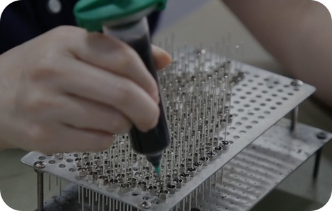
Tubular ceramic: A ceramic tube with metallized inner and outer surfaces. The conductor passes through the tube’s inner bore. This is one of the most common forms for panel-mount and chassis-mount EMI filter applications.
MLCC three-terminal: A multilayer ceramic capacitor with a three-terminal structure, available in surface-mount (SMT) configurations. The three-terminal geometry reduces shunt- path inductance compared to standard two-terminal MLCC devices. Used in PCB-level filtering applications.
Hermetically sealed military types: Feedthrough capacitors built to MIL-PRF-15733 qualification with glass-to-metal seals for extreme environmental robustness. Used in military, aerospace, and other high-reliability applications.
Multi-pin arrays: Multiple feedthrough capacitor elements in a single package, used where several signal or power lines require filtering at the same panel entry point.
Mounting styles include screw-type (threaded body, secured with nut and washer through a panel hole), solder-in (body soldered into a chassis hole), press-in, and PCB-mount. The mounting style affects both the quality of the chassis ground bond achievable and the assembly process required.
How a Feedthrough Capacitor Works in an EMI Filter Circuit
The Noise Shunt Path
In a panel-mount installation, the feedthrough capacitor is installed at the point where a conductor enters or exits a shielded enclosure. The through-conductor carries the desired signal or power current from the outside to the inside. High-frequency noise on the conductor is coupled capacitively to the outer electrode and shunted directly to the chassis at the panel wall.
Because the shunt occurs at the enclosure boundary — before the noise enters the interior of the shielded volume — filtered and unfiltered conductors are physically separated by the panel wall itself. This is a structural advantage over PCB-mount filter implementations, where the separation between the input and output sides depends entirely on layout discipline.
Filter Topology Options
A feedthrough capacitor alone is a C-type filter element — a single shunt capacitor. It provides common-mode noise attenuation over a frequency range bounded by the SRF of the component. For applications requiring broader attenuation bandwidth, suppression of both common-mode and differential-mode noise, or higher insertion loss over a wider frequency range, the feedthrough capacitor can be combined with series inductors to form L-C, Pi, or T-type filter networks. Complete feedthrough EMI filter assemblies integrate these elements into a single package.
Insertion Loss Interpretation
Published insertion loss curves for feedthrough capacitors are measured in standardized test fixtures, typically with 50Ω source and load impedances. Real-world attenuation in a circuit with different source and load impedances will differ from the datasheet curve. Use published insertion loss curves for comparative evaluation between components under consistent test conditions, and verify actual performance by measurement in the installed circuit.
Feedthrough Capacitor vs. Alternative Components
| Component | Suppression mechanism | HF effectiveness | Ground path needed | Typical use case |
| Feedthrough capacitor | Reactive shunt to chassis | High (low shunt-path ESL) | Yes — chassis or panel | Panel/chassis entry point filtering |
| Standard 2-terminal MLCC | Reactive shunt | Limited above SRF | Yes — PCB ground | PCB-level decoupling and low-frequency filtering |
| Ferrite bead | Resistive dissipation | Peaks at bead’s rated frequency, rolls off above | No chassis required | PCB power rails, signal lines without chassis bond |
| Common-mode choke | Inductive series impedance (common mode) | Effective over defined bandwidth | No chassis required | Differential signal lines, power entry filtering |
| Complete feedthrough filter assembly | Reactive network (LC, Pi, or T) | Broadest bandwidth | Yes — chassis or panel | High-attenuation panel entry filtering |
The key selection criterion is whether a low-impedance chassis ground bond is available at the filter location. Feedthrough capacitors and complete feedthrough filter assemblies require direct chassis bonding to function as intended. Ferrite beads and common-mode chokes do not — making them the appropriate choice for PCB-level suppression where no chassis bond is accessible.
Key Selection Parameters
Capacitance and SRF
Capacitance value determines the filter’s cutoff frequency in combination with any series inductance present in the circuit. SRF must be above the highest noise frequency of concern. Increasing capacitance lowers the SRF — the two parameters must be balanced for the specific application.
Dielectric Material
C0G (NP0) dielectric provides near-zero capacitance variation with temperature and minimal change under applied DC voltage. It is the preferred dielectric where consistent filtering performance across operating conditions is required, and is generally the more reliable choice for DC power line applications. X7R dielectric offers higher capacitance density but exhibits capacitance reduction under DC bias — which can shift the effective cutoff frequency in service. Z5U and Y5V dielectrics are generally not suitable for EMI filter applications due to high capacitance variation with temperature and voltage.
Voltage, Current, and Environmental Ratings
Voltage rating must be confirmed against the line voltage with appropriate margin. Current handling, operating temperature range, vibration tolerance, and ingress protection requirements depend on the installation environment and must be verified from the datasheet for the specific part number and construction type.
Installation Requirements
Ground Bond Quality
The feedthrough capacitor’s high-frequency performance depends on the impedance of the path from its outer electrode to chassis ground. For screw-type installations, this path goes through the metal-to-metal contact between the filter body and the panel wall — which requires the panel surface to be free of paint, anodizing, or oxidation, and the installation to be torqued to the manufacturer’s specified value. For solder-in installations, the ground bond is established through the solder joint at the chassis hole.
A poor-quality ground bond — from under-torque, surface contamination, or a cold solder joint — increases the impedance of the shunt path and reduces high-frequency attenuation. This is the most common installation failure mode for feedthrough capacitors, and it is not detectable by visual inspection alone.
Input and Output Side Separation
The filtered (output) side of the feedthrough capacitor must be kept physically separate from the unfiltered (input) side. In panel-mount installations, the panel wall provides this separation naturally. In PCB-mount implementations, layout discipline — separate routing of input and output side traces, with no parallel runs — is required to prevent noise from coupling around the filter.
Typical Application Areas
Feedthrough capacitors are used wherever a low-inductance shunt to chassis ground is needed at a conductor boundary — most commonly at panel or enclosure entry points:
- Power line entry filtering:AC and DC power lines entering shielded industrial equipment, control cabinets, and SMPS housings
- Signal and I/O panel feedthroughs:Sensor, control, and communication lines entering shielded enclosures in industrial automation and instrumentation equipment
- High-frequency RF suppression:Applications where noise frequencies extend above the range where standard two-terminal capacitors remain effective
- Military, aerospace, and medical equipment:Where rugged construction, MIL-spec qualification, or patient safety constraints require specifically qualified components
Conclusion
Feedthrough capacitors remain one of the most effective solutions for controlling conducted EMI at enclosure entry points — from industrial automation and power line entries to high-frequency RF suppression and MIL-spec applications. Their coaxial architecture provides a low-inductance shunt path that standard two-terminal capacitors cannot match at high frequencies.
Based on LCA’s experience supporting EMC-critical applications, successful EMI suppression depends not only on selecting the appropriate specifications, but also on proper installation, grounding quality, and layout practices. When these factors are considered together, feedthrough capacitors significantly improve system reliability, reduce EMC-related issues, and simplify compliance testing.
Frequently Asked Questions
Q: When should I use a feedthrough capacitor instead of a ferrite bead?
Feedthrough capacitors require a direct chassis ground bond at the installation point. Where that bond is available — at a panel wall, chassis bulkhead, or connector — feedthrough capacitors provide reactive shunting that remains effective to higher frequencies than ferrite beads above their impedance peak. Ferrite beads are more appropriate for PCB-level power rail and signal line suppression where no chassis bond is accessible.
Q: Does a larger capacitance value always provide better EMI filtering?
Not at high frequencies. Increasing capacitance lowers the SRF. If the higher-value component’s SRF falls below the noise frequency, it operates in its inductive region and provides less attenuation than a smaller capacitor with a higher SRF. For high-frequency applications, SRF must be evaluated alongside capacitance value.
Q: What dielectric should I specify for a feedthrough capacitor on a DC power line?
C0G (NP0) dielectric provides stable capacitance regardless of DC bias and is generally the more reliable choice for DC power line applications. X7R loses a significant fraction of its rated capacitance under DC bias. The magnitude of this loss depends on the specific part and the voltage ratio. Always review the DC bias derating curve from the manufacturer’s datasheet before selecting X7R for a DC power line application.
Q: Does the mounting style affect EMI performance?
Yes. The ground bond quality — established through torque and metal-to-metal contact in screw-type mounting, or through the solder joint in solder-in mounting — directly determines the impedance of the noise shunt path. A poor-quality bond of either type increases ground path impedance and reduces high-frequency attenuation. The mounting style also determines whether the filter is field-replaceable or permanently installed.
Recommended references
MIL-PRF-15733 / QPL references — Military feedthrough capacitor and EMI filter qualification.
Murata noise countermeasure with 3-terminal capacitors — Helpful for understanding low-inductance capacitor-based EMI suppression.
EMC/feedthrough application notes — Useful for grounding, installation, and chassis-bound filtering concepts.
Need Help with Feedthrough Capacitor Selection?
Every application is different — and so is every EMI challenge.
LCA’s engineering team can help you evaluate your noise spectrum. They will assess your EMC requirements and installation environment. Finally, they will recommend the most suitable feedthrough capacitor for your aerospace, military, or industrial application.
Contact LCA today for one-to-one technical support and customized EMI suppression recommendations.