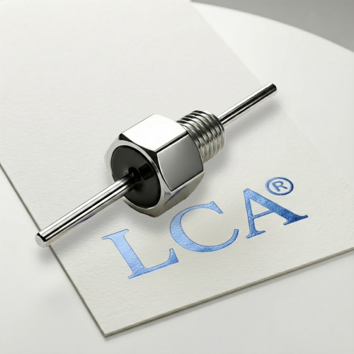
Solder-in EMI filters are a category of feedthrough suppression components designed to be permanently bonded to a chassis, panel, or shield wall by soldering. Because the filter body becomes part of the conductive enclosure, installation quality has a direct effect on
attenuation performance. A filter that is correctly specified but poorly installed may provide substantially less suppression than the datasheet suggests.
This guide covers what engineers need to know before, during, and after installation —
including PCB and chassis preparation, soldering process parameters, grounding requirements,and common failure modes. Yet the most critical steps happen before soldering begins.
Before You Start: Design-Phase Preparation
Mistakes in installation often trace back to decisions made at the design stage. Addressing these before the first solder joint reduces defect risk in production.
Read the Manufacturer’s Datasheet and Installation Guide
Failure to review these official documents upfront will lead to improper panel hole sizing, incompatible solder materials and incorrect soldering parameters. These issues will not only compromise mechanical assembly and grounding performance, but also degrade EMI filtering effects and shorten the service life of filters.
Mounting Hole Dimensions
Hole dimension and tolerance are strictly defined in the datasheet. Using undersized holes will force the component into place and crack the ceramic body, while oversized holes lead to loose fitting, unstable solder joints and elevated ground impedance. Both issues will impair mechanical reliability and EMI filtering performance. Confirm hole dimension at the design phase to avoid rework and performance issues.
Grounding Strategy
The filter case must make solid electrical contact with the chassis to provide the intended
noise suppression. In solder-in installations, this bond is established through the solder
joint itself. Before assembly, verify that:
- The chassis hole area is free of paint, anodizing, or oxidation that would prevent solderwetting.
- The chassis material is compatible with the recommended solder alloybodyand the enclosure wall.
- Verify the chassis plating material (e.g., tin or nickel plating) is solderable.
- Standard aluminum or stainless steel panels cannot be directly soldered without specialized plating or flux.
Step-by-Step Installation Guide
Step 1 — Verify Component and Hole Condition
Inspect the filter body for visible damage before starting. Confirm the chassis hole dimensions are within the tolerance specified for the specific part. Ensure the hole area and filter body are clean and free of contamination, oxidation, or surface coating that would impair solder wetting.
Step 2 — Select Solder Alloy
RoHS / lead-free status must be established before selecting a solder alloy. In most industrial, commercial, and automotive applications as of the current regulatory environment, lead-containing solder is restricted under RoHS and REACH directives. Leaded alloys are only permissible where an explicit exemption applies. Confirm the regulatory status of your end product before proceeding.
Step 3 — Preheat the Assembly
Rapid temperature changes thermally stress the internal ceramic capacitor element and can cause micro-cracking that may not be immediately visible but will shorten component life.However, the effectiveness of preheating depends heavily on the thermal mass of the chassis.
Chassis thermal mass is a critical factor. A typical industrial chassis — thick aluminum plate, steel, or galvanized sheet — conducts heat away from the joint area very rapidly. Preheating only the area immediately around the mounting hole is often insufficient, because thermal energy dissipates into the surrounding metal before soldering can be completed. For large or thermally conductive chassis materials, the recommended approach is to preheat the entire panel or chassis section on a hot plate or in a convection oven to approximately 100–130°C, then complete the solder joint quickly while the chassis retains heat. This approach reduces the temperature differential (ΔT) between the iron tip and the work surface, which in turn reduces thermal shock risk to the component.
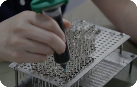
Step 4 — Solder the Filter Body to the Chassis
Position the filter in the chassis hole. Apply solder using a controlled process. Regardless of alloy, use a heat sink adjacent to the filter body where possible to limit heat transfer into the component internals. Do not hold or leverage the filter body with pliers or similar tools — lateral mechanical force during soldering can deform internal structures or crack the ceramic capacitor element.
Step 5 — Solder the Terminals (if applicable)
Some solder-in filter designs require separate soldering of the signal or power terminals in addition to the chassis body joint.
Recommended practice:
- Ensure the chassis is at a stable temperature from Step 4 before proceeding to terminals
- Use the minimum tip temperature and dwell time that achieves full terminal wetting
- Maximum dwell: 3 seconds as a conservative starting point
- Do not apply mechanical stress to the terminals while the solder joint is cooling
Step 6 — Inspect the Completed Joint
A properly completed solder joint should show full wetting around the filter-to-chassis interface with no visible gaps, cold spots, voids, or excess solder bridging. The filter body should be fully seated with no visible gap between the body flange and the chassis surface.
Common Installation Mistakes
| Mistake | Effect | How to avoid |
| Excessive iron dwell time | Internal capacitor damage; reduced insertion loss | Follow manufacturer dwell limits; use heat sink |
| Fast temperature ramp | Thermal shock cracking | Preheat chassis; limit ramp rate |
| Poor chassis surface prep | Weak mechanical bond; high ground impedance | Clean chassis hole area before assembly |
| Holding filter with pliers | Mechanical deformation | Use appropriate fixtures; do not apply lateral force |
| Wrong solder alloy | Unreliable joint; possible incompatibility | Verify alloy specification from datasheet |
| Cross-applying another product’s process | Out-of-spec installation | Use only the specific product’s installation guide |
Verification After Installation
Visual and Mechanical Inspection
Check that the filter body is fully seated in the chassis hole with an even solder fillet
around the perimeter. Confirm there is no movement when gentle lateral pressure is applied.
Insertion Loss Verification
For critical applications, insertion loss can be spot-checked using a network analyzer or
spectrum analyzer with a controlled test fixture. Measured values in a production installation may differ depending on chassis geometry, lead routing, and ground path quality. A significant deviation from the datasheet curve warrants investigation of the ground bond and solder joint quality before concluding the component itself is defective.
Pre-Compliance EMC Scan
If the installation is part of a design being validated for CE, FCC, or similar certification,
a conducted emissions pre-scan after installation provides useful early-stage feedback. A
properly installed solder-in EMI filter should reduce conducted emissions at the frequencies covered by its rated insertion loss band. If the pre-scan shows limited improvement, re-examine solder joint quality and chassis bonding before modifying the circuit.
Rework and Removal
Solder-in installations are intended to be permanent. Rework is possible but carries risks:
- Repeated heating cycles can damage the internal MLCC capacitor element
- Mechanical stress during removal can crack the filter body
- The chassis hole may require re-finishing after desoldering
- Control iron temperature and dwell time with the same care as initial installation.
- Operationsshould be performed by trained personnel in an ESD-protected environment.
Frequently Asked Questions
Q: Can I use a standard soldering iron to install a solder-in EMI filter?
Yes, but only within the temperature and dwell-time limits specified by the manufacturer.
Q: Do I need to solder both the filter body and the terminals?
It depends on the specific part design. Some solder-in filters require body soldering to the
chassis and separate terminal soldering for the signal or power connection. Others only
require one operation. Confirm the assembly requirements from the product’s datasheet and installation guide.
Q: Is solder-in the same as press-in mounting?
No. Solder-in and press-in mounting are distinct installation categories for feedthrough filters. Press-in installation does not require solder. Installation procedures for one type must not be applied to the other without verification.
Q: Why does grounding quality affect EMI performance so much?
The filter’s noise suppression depends on establishing a low-impedance path from the signal conductor to the chassis. If the solder joint between the filter case and the chassis is incomplete — due to surface contamination, insufficient wetting, or cold solder — the ground path impedance increases and attenuation decreases, particularly at higher frequencies.
Q: Can I use the same installation procedure for filters from different manufacturers?
Not reliably. Hole tolerances, solder alloy requirements, temperature limits, and dwell times are part- and vendor-specific. One manufacturer’s published process data should not be reused for a different manufacturer’s product without confirmation from the second manufacturer’s documentation.
Q: Will correct installation guarantee the product passes EMC testing?
No. Correct installation is a necessary condition for achieving the filter’s rated performance,but system-level EMC compliance depends on the full product design — enclosure integrity,cable routing, PCB layout, and grounding architecture. The filter must be evaluated in the context of the complete system.
Need Help installing Solder-in feedthrough capacitors?
Every installation is different — and so is every EMI challenge.
LCA’s engineering team can help you evaluate your noise spectrum, EMC requirements, and installation environment to recommend the most suitable feedthrough capacitor or EMI filter solution.
Contact LCA today for one-to-one technical support and customized EMI suppression recommendations.