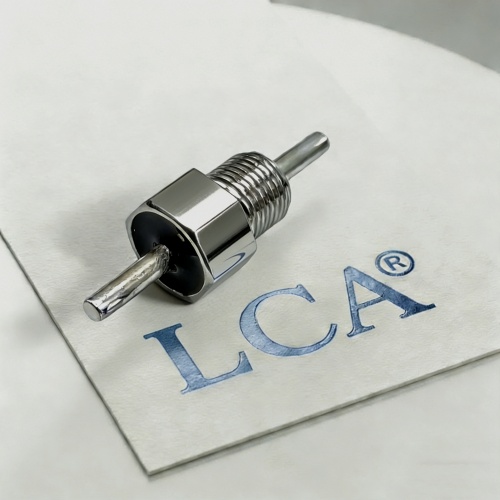
An EMI filter can meet its datasheet and pass incoming inspection, then fall short once it is installed. In many cases, the cause is not the nominal capacitance or the filter design. It is the installation: a poor ground bond, excessive mounting force or torque, an uncontrolled soldering process, or a layout that lets noise couple around the filter. High-density assemblies tend to make each of these more likely.
This guide is for OEM engineers who define mounting, soldering and layout requirements for feedthrough and other EMI filters. It describes common failure modes and how to address them in drawings, specifications and incoming inspection. It does not give torque values, soldering profiles or spacing figures. These depend on the specific part, the governing drawing and your program requirements, and should be taken from the manufacturer’s guidance.
Quick Answer:
EMI filter installation failures can result from poor chassis bonding, excessive mounting force or torque, uncontrolled soldering, inadequate input-output separation and improper grounding. To prevent these problems, engineers should follow the manufacturer’s installation limits, define conductive contact surfaces, maintain short and direct RF ground paths, separate filtered and unfiltered conductors, and control soldering and cleaning processes. Installation requirements should be documented in engineering drawings and assembly specifications, with final filter performance verified in a representative system configuration.
Why Installation Problems Are Often Mistaken for Component Defects
Component Data vs. Installed Performance
Datasheet insertion loss is usually measured in a standardized fixture with defined impedance and grounding, for example under CISPR 17 or MIL-STD-220. That is useful for comparing parts, but it is not a prediction of performance in your assembly. Source and load impedance, bonding quality, cable routing and layout all affect what the filter delivers once installed.
Why High-Density Assemblies Raise the Risk
Dense layouts can bring shared ground paths, longer return routes, nearby noise sources, limited thermal relief and restricted access during assembly or rework. These conditions increase mechanical stress, make good bonding harder to achieve, and make coupling between filtered and unfiltered conductors more likely.
Separating Component Faults from Installation Faults
When a filter underperforms after assembly, the corrective action depends on whether the cause is the component or the installation. A structured failure analysis helps. Responsibility depends on the contract, the analysis result and whether supplier guidance was followed, so it is worth agreeing on the process before a problem occurs.
Common Installation Failure Modes
| Failure mode | Possible causes | Prevention approach |
| Cracked ceramic or case | Excessive torque, board flexure, mechanical shock | Use the manufacturer’s torque limit and support adjacent wiring and boards |
| Thermal damage | Uncontrolled soldering, reflow or rework | Follow the supplier’s permitted process and limit rework |
| Poor chassis bond | Paint, anodizing or oxide on the contact surface; long ground wire | Define contact surface requirements on the drawing |
| High RF impedance ground | Indirect ground path, poor solder joint, inductance | Keep ground connections short and direct; inspect joints |
| Input–output coupling | Filtered and unfiltered conductors routed close together | Separate the two sides physically and avoid parallel runs |
| Loss of shield continuity | Gaps at the enclosure penetration | Maintain shield termination at each penetration |
| Seal damage | Mechanical or thermal stress on hermetic or sealed designs | Follow handling, torque and soldering limits for the specific part |
| Contamination issues | Flux residue or incompatible cleaning agents | Confirm process compatibility with the supplier |
Two points are worth emphasizing. First, a cracked ceramic element caused by over-torque may not be detected by ordinary post-installation checks and can lead to later failures. Second, in some filter constructions, internal soldered connections can reflow during installation, so the soldering process matters beyond the external joint.
Need Technical Support for EMI Filter Installation?
Proper installation is essential for achieving the expected EMI suppression performance. Mounting torque, grounding contact, soldering conditions and input-output separation should all be considered during the design and assembly process.
LCA MIC has focused on EMI suppression components, including ceramic feedthrough capacitors and EMI filter solutions for OEM applications.
If you are developing a new assembly or troubleshooting an existing EMI filter installation, our team can review the available product specifications and mechanical requirements to support a preliminary technical discussion.
For an initial review, please share:
- EMI filter part number or datasheet
- Mechanical drawing and mounting details
- Grounding and bonding arrangement
- Soldering and assembly process
- Operating voltage, current and temperature
[Contact LCA MIC for Technical Assistance]
Mechanical Mounting Requirements to Define
Mounting requirements belong on the drawing or assembly specification, not only in a supplier’s application note.
| Item | What to define |
| Mounting style | Threaded, solder-in, flange or panel mount, with hole preparation and panel thickness |
| Torque | Maximum torque and any torque control method, taken from the supplier’s specification |
| Hardware | Washers, gaskets, nuts and thread engagement |
| Support | Strain relief for adjacent wiring and support for nearby boards |
| Sealing | Gasket or sealing method where the enclosure requires it |
| Accessibility | Whether the tooling and access are adequate for the specified procedure |
Strict adherence to the manufacturer’s recommended torque matters, because the limit varies with the part and its construction. A value used for one filter should not be applied to another.
Grounding and Bonding Requirements
For bulkhead-mounted feedthrough filters, the path from the filter case to the chassis largely determines high-frequency performance.
- Contact surface:Specify bare, clean, conductive metal at the mating area. Avoid relying on paint, anodizing or oxide layers, and define any masking required on the panel.
- Ground path:Direct metal-to-metal or soldered contact is generally preferable to a long wire ground, which adds inductance.
- DC resistance is not enough:A connection can show acceptable DC resistance but still have high impedance at RF because of inductance, contact geometry or oxide. A DC continuity check therefore does not confirm that the filter is working.
- Shield termination:Maintain shield continuity at the penetration so that exposed shields do not bypass the filter.
- PCB ground planes:A plane does not replace a direct bond for a chassis-mounted feedthrough filter. For PCB-level filters, ground connections placed immediately adjacent to the shunt capacitor, with short, wide connections and adequate vias to a continuous reference plane, help keep inductance low. Avoid thermal relief on filter ground connections where the design allows.
Soldering and Assembly Process Constraints
Ask the supplier which processes the part is qualified for, and write the permitted ones into the assembly specification.
- Methods and limits:hand soldering, wave, reflow or other methods, with the thermal limits and exposure times the supplier specifies.
- Preheat and thermal shock:control temperature changes in line with supplier guidance.
- Joint quality:inspect solder joints to the workmanship standard your program invokes (for example IPC J-STD-001 where applicable). A poor ground joint may not be visible externally yet can reduce high-frequency attenuation.
- Cleaning and flux:confirm compatibility of flux and cleaning agents with the part and, for sealed designs, with the seal.
- Rework:define whether rework is permitted and how many thermal cycles the part can tolerate.
Process changes such as a different solder, cleaning agent, fastener or profile can fall outside what the supplier has validated, so they should be communicated.
Layout and Spacing in High-Density Assemblies
| Area | Requirement to consider |
| Input–output separation | Keep the unfiltered and filtered sides physically apart; bulkhead mounting uses the enclosure wall for this |
| Routing | Avoid parallel routing across the filter boundary and avoid sharing vias between the two sides |
| Reference plane | Maintain a continuous plane beneath the filter area; splits and slots force return current into larger loops |
| Cable routing | Segregate filtered and unfiltered cables and maintain shield continuity |
| Clearance and creepage | Apply the governing safety and PCB standards for your voltage, pollution degree and environment; generic tables may not be sufficient |
| Thermal | Check filter temperature at worst-case load, since high temperature can degrade capacitance and insulation resistance |
| Access | Make sure installation and inspection are physically possible |
Locate the filter as close as practical to the point where the line enters or leaves the shielded enclosure. Close routing of input and output to save space can allow capacitive or inductive coupling that bypasses the filter.
What to Ask Suppliers
| Topic | Question |
| Installation guidance | Is there a documented installation and handling procedure for this part? |
| Torque and mechanical limits | What are the limits, and what is their test basis? |
| Soldering | Which soldering methods and thermal conditions are permitted, and what are the rework limits? |
| Cleaning | Which flux and cleaning processes are compatible? |
| Grounding | What contact surface and ground path does the supplier assume for the published data? |
| Failure modes | What failure modes are known for this construction, and is failure analysis support available? |
| Qualification | Does any qualification or program approval apply to the exact part, including installation instructions? |
Do not assume guidance for one product applies to another. Limits depend on the part number and construction.
Common Specification and Procurement Gaps
| Gap | Why it matters |
| Electrical parameters specified, but no mounting or grounding requirements | Installed performance depends on both |
| No supplier installation guidance obtained | Torque and process limits are part-specific |
| Assuming one supplier’s torque or soldering advice applies to all parts | Limits vary by construction |
| Incoming inspection checks only capacitance | Mechanical damage and bonding issues may be missed |
| Process changes not communicated | Changes may exceed validated conditions |
| No failure analysis process agreed | Responsibility becomes unclear after a failure |
Frequently Asked Questions
Why does an EMI filter perform worse after installation than on the datasheet?
Datasheet data is measured under standardized conditions. In the assembly, grounding, layout, coupling and any installation damage can all affect the result, so verify in a representative setup.
Why can a filter pass incoming inspection and still fail after assembly?
Internal solder joints in some constructions can reflow during installation, and over-torque can cause cracks that ordinary post-installation checks may not detect.
Is there a standard mounting torque for feedthrough filters?
No general value. Limits depend on the part, thread and construction, and should come from the supplier’s specification.
Can I use any soldering process for EMI filters?
Not necessarily. Confirm the permitted methods, thermal conditions and rework limits with the supplier.
Is DC resistance a sufficient measure of ground quality?
No. A connection with acceptable DC resistance can still have high RF impedance.
What should incoming inspection cover?
Typically identification and traceability, mechanical and visual checks, and the electrical items your quality and engineering teams select based on the specification.
Who is responsible if a filter fails after assembly?
It depends on the contract, the failure analysis and whether supplier guidance was followed. Agree on the process in advance.
Does a correctly installed filter guarantee my product will pass EMC testing?
No. Correct installation helps the filter perform as intended, but compliance must be verified on the finished equipment.