Correct Selection and Application of Electromagnetic Compatibility Components
In a complex electromagnetic environment, every electronic and electrical product must withstand a certain level of external electromagnetic interference (EMI) to function properly. At the same time, it must not generate electromagnetic interference that exceeds the tolerance of other nearby products. This requires meeting both electromagnetic sensitivity limits and electromagnetic emission limits as outlined by relevant standards. Achieving this balance is crucial for ensuring electromagnetic compatibility (EMC) and obtaining certification for electronic and electrical products.
Many engineers face challenges when selecting and using EMC components during product design. It is important to understand the components' characteristics in order to design electronic and electrical products that meet standards while optimizing performance and cost. Below, we explore common EMC components and circuit design techniques used to reduce or suppress electromagnetic interference.
Components Group
There are two primary groups of electronic components: leaded and leadless components. Leaded components have parasitic effects, especially at high frequencies. Each pin introduces a small inductance (~1nH/mm/pin) and a capacitive effect (~4pF). Therefore, minimizing the length of the pins is important for reducing these parasitic effects.
In contrast, leadless and surface-mount components exhibit smaller parasitic effects, with typical values around 0.5nH for parasitic inductance and ~0.3pF for terminal capacitance. For electromagnetic compatibility purposes, surface-mount components are the most effective, followed by radial lead components, and finally, axial parallel lead components.
1. Capacitors in EMC Components
Capacitors are among the most commonly used components in EMC design. They are primarily used to create low-pass filters, decouple circuits, and bypass signals. Proper selection and use of capacitors can effectively solve many EMI issues while offering a low-cost and efficient solution. However, improper selection may exacerbate EMI problems.
In theory, larger capacitance values offer better filtering, but capacitors with larger capacitance also tend to have larger parasitic inductances and lower self-resonant frequencies. For example, a typical ceramic capacitor with a capacitance of 0.1 μF has a self-resonant frequency of around 5 MHz, while a 0.01 μF capacitor resonates at around 15 MHz. Capacitors with these characteristics can perform poorly in decoupling high-frequency noise, especially above 10 MHz.
To address these challenges, capacitors with special structures, such as chip capacitors, are preferred for RF applications. These capacitors have negligible parasitic inductance and a much higher self-resonant frequency, making them ideal for high-frequency applications (up to 200 MHz or more).
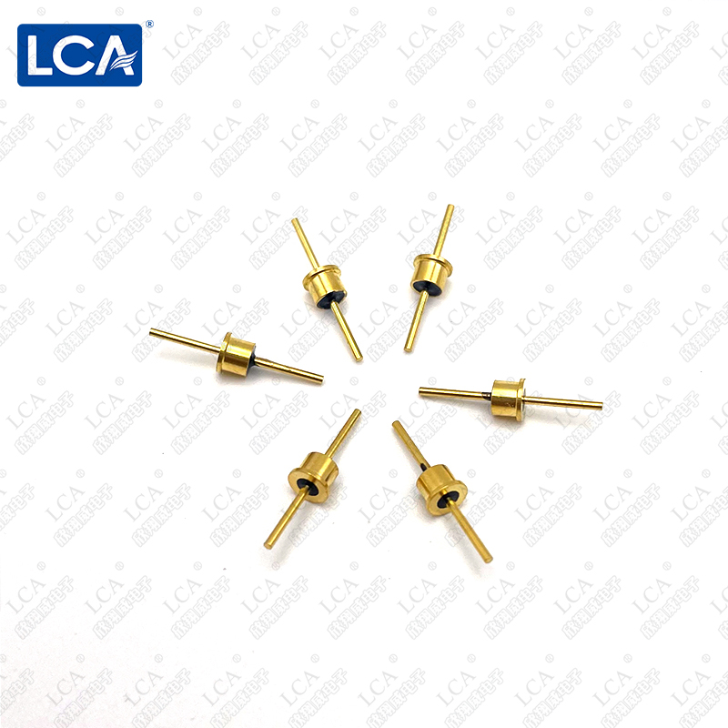
For VHF and higher frequency ranges, feed-through capacitors are used to suppress noise and protect shields from penetration.
2. Inductors in EMC Components
Inductors are components that can create a magnetic field, making them sensitive to EMI. Like capacitors, they can be used to address various EMC challenges. There are two main types of inductors: open-loop and closed-loop. In an open-loop design, the magnetic field is controlled by air, which can cause radiation and EMI issues. In contrast, closed-loop inductors completely control the magnetic field within a core, which helps minimize EMI radiation.
Inductors are typically made from two core materials: iron and ferrite. Ferrite core inductors are used for high-frequency applications (up to MHz), making them particularly well-suited for EMC applications.
In EMC applications, special inductors such as ferrite beads and ferrite clips are commonly used. Ferrite core inductors are most effective for high-frequency noise suppression.
3. The Choice of Filter Structure
Filters in EMC design are usually low-pass filters composed of inductors and capacitors (L-C filters). The filter's effectiveness depends not only on its structure but also on the impedance of the connected network. For example, a filter with a single capacitor works well in high-impedance circuits but performs poorly in low-impedance circuits.
Filter Classification
Filters can be classified based on either function or structure:
- Function-based classification: filters designed to block certain frequencies or reduce EMI.
- Structure-based classification: different arrangements of capacitors, inductors, and resistors to achieve optimal filtering performance.
Filter Selection
When selecting filters for EMC design, consider the frequency range, impedance, and placement within the circuit. Proper selection ensures that the filter meets the system's needs and effectively mitigates EMI without introducing additional noise.
4.Magnetic Beads and Diodes for EMC: Selection, Application & Design
Learn about magnetic beads and diodes for EMC, their selection and applications in reducing EMI, improving signal integrity, and enhancing electromagnetic compatibility.
5.What are Magnetic Beads?
Magnetic beads are composed of an oxygen magnet, with the inductance being made up of a magnetic core and a coil. The magnetic bead converts AC signals into heat energy, while the inductance stores and gradually releases AC signals. Magnetic beads are typically used in signal circuits to absorb UHF signals, commonly found in RF circuits, PLLs, oscillating circuits, and UHF memory circuits like DDR, SDRAM, and RAMBUS.
6.Magnetic Bead Selection
Magnetic beads are different from inductors in their frequency characteristics. While inductors store energy, magnetic beads convert and dissipate energy, making them ideal for suppressing EMI in signal lines. Magnetic beads are commonly used in power input parts to improve EMI performance in high-frequency circuits.
7.Diodes for EMC
Diodes are simple semiconductor devices that help solve EMC-related problems due to their unique characteristics. Specific types of diodes can prevent and mitigate electromagnetic interference by controlling signal flow and reducing noise. Diodes play a crucial role in both conducted and radiated interference suppression in EMC design.
8.Selection of Active Devices for EMC
Active devices, including analog and logic devices, must be carefully chosen to manage electromagnetic emissions and sensitivity. The sensitivity characteristics of analog devices depend on inherent noise, while logic devices are selected based on their noise tolerance and immunity. Reducing transient ground current and using decoupling capacitors are essential for minimizing EMC issues in these devices.
9.Surface Mount Technology (SMT) in EMC Design
Surface Mount Technology (SMT) is an advanced assembly technology used in electronics, including computer, communications, and military applications. SMT helps address EMC challenges by reducing the size of components and enhancing circuit board integration, offering better solutions for electromagnetic emissions and sensitivity problems in miniaturized circuits.

